
1
General information

2
Technical information
3
Safety information
4
Storage information
5
Information regarding discharge of liquids
6
Information for replacing the functional units
7
Information for disassembly
8
Information about overhauling
9
Assembly information
10
Fluids filling information
11
Information about optional components
12
Information on adjustments
13
Tools information
14
Information about failures
15
Glossary

Lubrication circuit
|
2.10.1 Lubrication circuit diagram
Tab 2.22
|
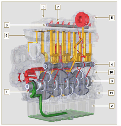 Fig 2.16 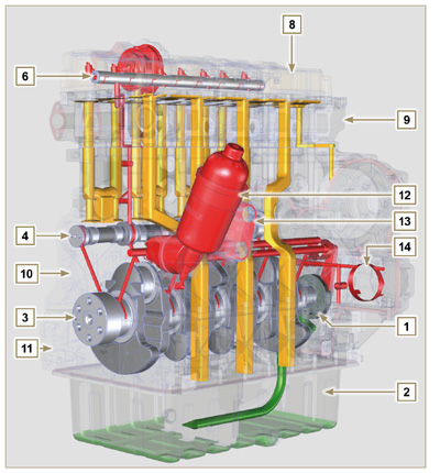 Fig 2.17 |
||||||||||||||||||||||||||||||||||||||
|
NOTE: Click by side to play the procedure. |
"> | ||||||||||||||||||||||||||||||||||||||
|
2.10.2 Oil pump
|
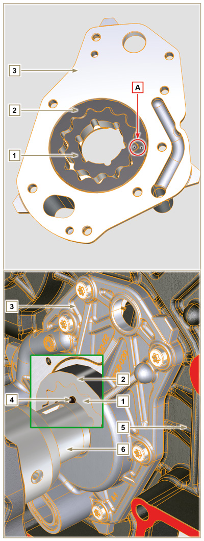 Fig 2.18 |
|
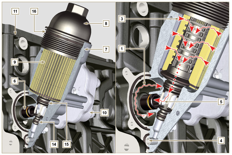
2.10.3 Oil filter and Oil Cooler
Fig 2.19 |
|||||||||||||||||||||||||||||||||||||||||||||
Tab 2.24
Tab 2.25 Cartridge characteristics.
|
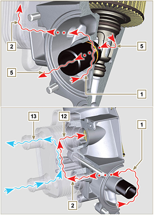 Fig 2.20 |
||||||||||||||||||||||||||||||||||||||||||||

 Loading