
1
General information

2
Technical information
3
Safety information
4
Storage information
5
Information regarding discharge of liquids
6
Information for replacing the functional units
7
Information for disassembly
8
Information about overhauling
9
Assembly information
10
Fluids filling information
11
Information about optional components
12
Information on adjustments
13
Tools information
14
Information about failures
15
Glossary

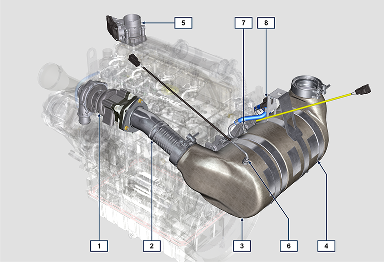
Intake and exhaust circuit
|
2.12.1 Turbocharger
 Important Important
Tab 2.31
|
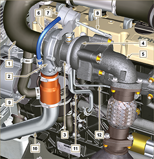 Fig 2.27 |
||||||||||||||||||||||||||
|
2.12.2 ATS device
2.12.2.1 DOC
Important
Tab 2.32a
|
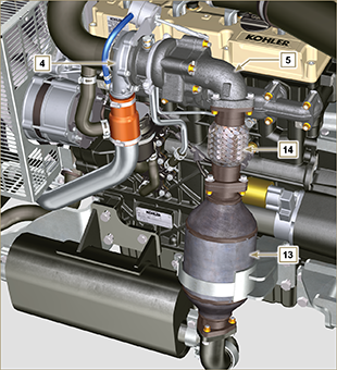 Fig 2.28 |
||||||||||||||||||||||||||
|
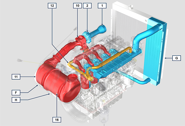
2.12.2.2 Intake and exhaust circuit diagram with DOC
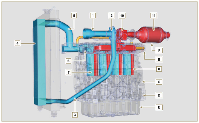 Fig 2.29 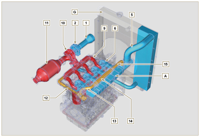 Fig 2.30 |
|||||||||||||||||||||||||||
Important
The EGR circuit is furnished with a heat exchanger (EGR Cooler), which cools the recovered Gases (this process enables better performance during combustion inside the cylinders). |
Tab 2.32b
|
||||||||||||||||||||||||||||||||||||||||||||||
|
2.12.2.3 DOC+DPF
The DOC+DPF system reduces emissions because the DPF eliminates the particulate generated by Diesel fuel combustion. The system triggers automatic DPF regeneration cycles depending on the degree of clogging. The smell of the gases out of the exhaust line is different than the traditional one of gases from Diesel engines. Moreover, during regeneration stages, the exhaust gases could temporarily be white.
NOTE: During regeneration, engine idling will increase.
Fig 2.30a |
|||||||||||||||||||||||||||||||||||||||||||||||
|
Tab 2.32c
|
|||||||||||||||||||||||||||||||||||||||||||||||
|
2.12.2.4 DPF regeneration strategy
You can intervene on the machine control panel for the DPF regeneration operations "only if requested by means of specific warning lights or messages on the control panel".
Tab. 2.32d describes the level of particulate accumulation, the relationship with the warning lights that will light up on the panel, the performance limitations of the engine and the operator’s options intervention.
Forced regeneration must be executed in accordance with the machine instructions.
Tab 2.32d
*1: The warning lights be different – consult the machine manual. *2: Unless stated otherwise in the machine manual.
 Warning Warning
|
|||||||||||||||||||||||||||||||||||||||||||||||
| 2.12.2.5 Intake and exhaust circuit diagram with DOC+DPF
Tab 2.32e
|
|||||||||||||||||||||||||||||||||||||||||||||||
|
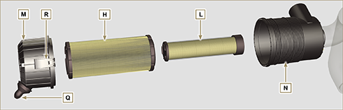
2.12.3 Air filter
Important
|
Tab 2.33
|
||||||||||||||||||||||||||||||||||||||||||||||


 Loading