=
Search

Electric system

2.13.1 ECU input and output signals diagram  

SENSOR/SWITCH (INPUT)   DEVICES (OUTPUT)
Power relay ECU Electronic injector 1
Engine Revolution Sensor Electronic injector 2
Engine phase sensor Electronic injector 3
Coolant temperature sensor Electronic injector 4
Common Rail pressure sensor EGR valve control
Oil pressure switch Fuel intake adjustment valve
EGR valve position Revolution indicator
Fuel temperature sensor Heater relay
T-MAP sensor Diagnosis indicator lights
ACACT Sensor Throttle body adjustment
Main accelerator pedal (double track) Electric fan control (1-2 speeds or variable speed)
 Secondary accelerator pedal (optional) CAN 1 (ISO15765 diagnostics)
 Hydraulic oil pressure sensor (optional) CAN 2 (Vehicle SAE J1939)
Fuel level sensor (optional)         
Air filter clogging sensor (optional)
Sensor to detect water in the fuel
Throttle body position
EGTS (black) Sensor
EGTS (yellow) Sensor
Delta-P Sensor

2.13.2 Control unit (ECU)


The ECU is a central processor, which monitors and controls engine operation.
The electronic control unit is responsible for engine management.
It is fitted on the frame of the vehicle, or in the cab (refer to the technical documentation of the vehicle).


  Important
  • The ECU must only be used with the configuration defined
    by KOHLER, for each individual engine.
  • To look up ECU errors, refer to the Help File manual
2.13.2.1 Technical features
  • Operating temperature: -40°C - +100°C.
  • Storage temperature: -40°C - +100°C.


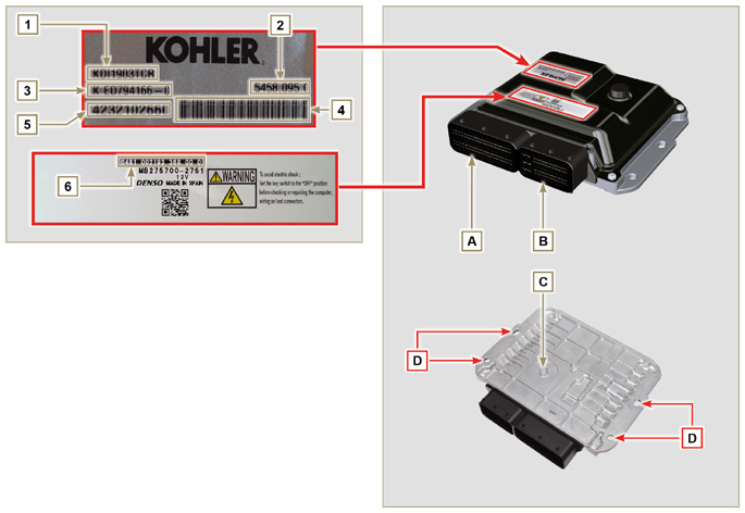
Fig 2.32 - Fig  2.33


Tab. 2.35

ECU AND ENGINE IDENTIFICATION PLATES
POS. DESCRIPTION
1

Engine model

2 Validation code
3 Engine specifications
4 Bar Code of the engine chassis number
5 Engine chassis number
6 ECU identification code
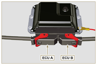
A Connector A (ECU A)
B Connector B (ECU B)
C Barometric capsule
D Fastening points


  • Do NOT mount or replace the control unit with that of another engine.
  • Although externally each ECU seems to be identical, internally they are specifically configured only for use on the engine that they are supplied with.
  • To install a new control unit, is required to recharge on it's the original configuration relating to that specific engine.
  • The control units are not interchangeable nor modifiable.
  • Each control unit is accompanied by its adhesive identification plate.

2.13.3 Engine electrical wiring


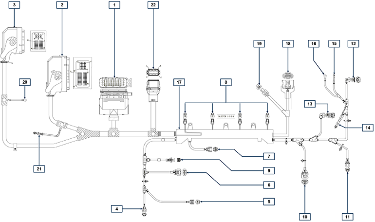
Fig 2.34

Tab. 2.36

RIF. DESCRIZIONE
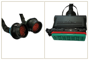
1 Vehicle interface connector (Fig. 2.34a)
2 ECU Connector A (Fig. 2.34b)
3 ECU Connector B (Fig. 2.34b)
4 Fuel pressure regulating valve connector
5 Fuel temperature sensor connector
6 T-MAP sensor connector
7 Common Rail pressure sensor connector
8 Injectors connectors
9 EGR valve connector
10 Engine speed sensor connector
11 Engine phase sensor connector
12 Oil pressure switch connector
13 Coolant temperature sensor connector
14 D+ Connector Alternator
15 Starter motor connector (50)
16 Starter motor connector 3,2kW (50)
17 Wiring support  
18 ETB connector (Stage V versions only)
19 ACACT connector (Stage V versions only)
20 Ground
21 CAN resistor
22 ATS wiring connector (Stage V versions only)
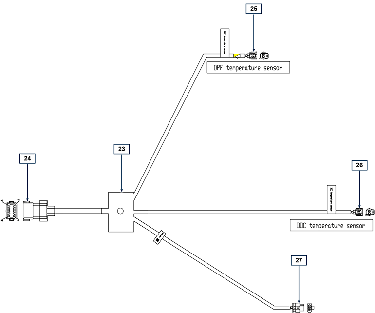
23 ATS interface wiring (Stage V versions only)
24 Engine wiring connector
25 DPF temperature connector (yellow)
26 DPF temperature connector (black)
27 Delta-P sensor connector


Fig 2.34a


Fig 2.34b

NOTE: Click by side to play the procedure.

2.13.3.1 Wiring disconnection

All sensor connectors and electronic control devices are sealed.
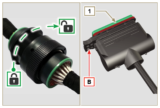
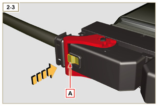
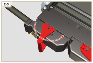
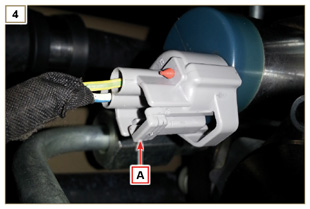
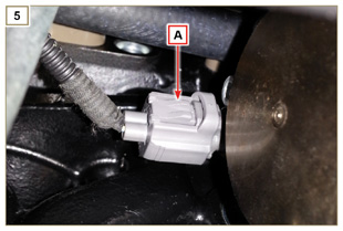
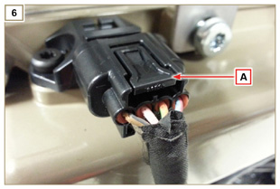
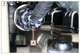
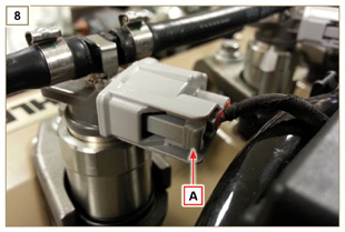
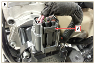
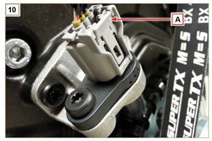
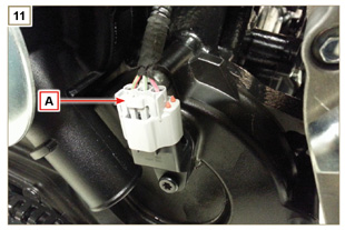
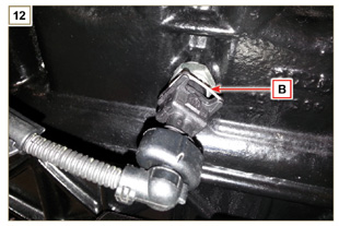
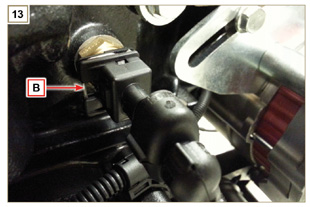
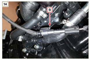
The connectors must be disconnected by means of pressure on tabs A or unblock the retainers B, as illustrated from Fig. 2.34c to Fig. 2.34r.

Fig 2.34c

Fig 2.34d

Fig 2.34e

Fig 2.34f

Fig 2.34g

Fig 2.34h

Fig 2.34i

Fig 2.34l

Fig 2.34m

Fig 2.34n

Fig 2.34o

Fig 2.34p

Fig 2.34q

Fig 2.34r
 
Wait Loading