
1
General information

2
Technical information
3
Safety information
4
Storage information
5
Information regarding discharge of liquids
6
Information for replacing the functional units
7
Information for disassembly
8
Information about overhauling
9
Assembly information
10
Fluids filling information
11
Information about optional components
12
Information on adjustments
13
Tools information
14
Information about failures
15
Glossary

Electrical components
| 2.15.1 Alternator (A) Externally controlled by the crankshaft by means of a belt.
|
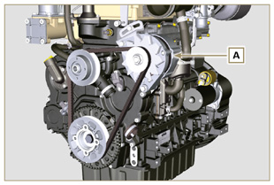 Fig 2.43 |
||||||||||||||||||||||||||||||||||
| 2.15.2 Alternator for Poly-V belt (optional) (B) Externally controlled by the crankshaft by means of a belt.
|
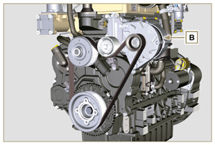 Fig 2.44 |
||||||||||||||||||||||||||||||||||
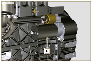
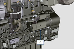
2.15.3 Starter Motor (C)
|
Fig 2.45b |
||||||||||||||||||||||||||||||||||
|
2.15.4 EGR Valve (D) Characteristics:
|
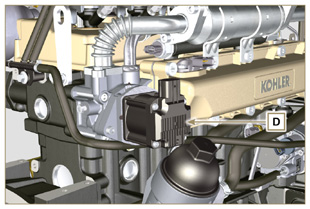 Fig 2.46 |
||||||||||||||||||||||||||||||||||
|
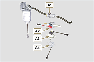
2.15.5 Cold starting device (Heater)
|
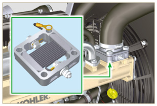 Fig 2.47 |
||||||||||||||||||||||||||||||||||
|
2.15.6 Fuel intake regulating valve (SCV)
 Important Important
|
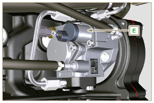 Fig 2.47 a |
||||||||||||||||||||||||||||||||||
|
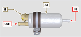
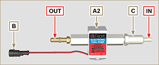
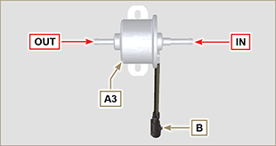
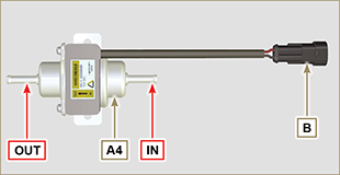
2.15.7 Electric fuel pump (optional)
NOTE: Component not necessarily supplied by KOHLER.
Tab. 2.39
Tab. 2.39a
Tab. 2.39b
Tab. 2.39c
Tab. 2.39d
|
Fig 2.48
Fig 2.48a
Fig 2.48b
Fig 2.48c
Fig 2.48d |
||||||||||||||||||||||||||||||||||
|
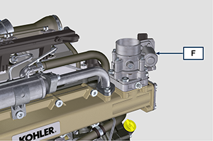
2.15.8 ETB (versions with DOC+DPF device - Stage V only)
The ETB valve F is controlled by the ECU during the DPF filter regeneration strategies. |
Fig 2.48e |

 Loading