|
6.7.1 Refrigerant pump disassembly
- Perform the operations described in Par 6.5.1.
6.7.2 Crankshaft and target wheel pulley disassembly
- Perform the operations described in Par 6.6.1.
- Disconnect the connector AE from the sensor S.
|
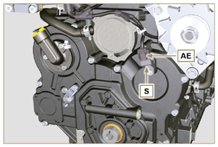
Fig 6.49 |
|
6.7.3 Timing system crankcase disassembly
 Important Important
- Perform the operations described in Par. 5.2.
- Make sure that the reference pin A is facing upwards.
- Undo the screw H (ST_06) and remove the sensor S.
- Undo the screws B and remove the timing system crankcase C.
|
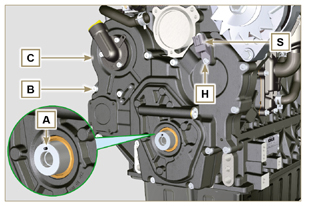
Fig 6.50 |
|
6.7.4 Oil pump disassembly
- Undo the screws D (ST_06) and remove the group pump E from the timing system crankcase C.
- Remove the rotors F and G from the oil pump crankcase E.
|
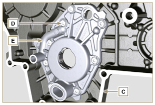
Fig 6.51
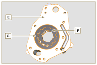
Fig 6.52
|
|
6.7.5 Oil pump assembly
NOTE: Carry out the checks described in Par. 8.7 prior to assembly.
- Check that all surfaces in contact between F, G, H, E and C are free from impurities - scratches - dents.
- When assembling, do not use any type of gasket between E and C.
- Thoroughly lubricate the seat of the rotors H on the oil pump crankcase E and the two rotors F and G.
- Within housing H insert the 2 rotors (in sequence) G and F, observing the references BP as described in figure (or refer to Par. 2.10.2).
- Check that the 2 pins L are inserted properly in the timing system crankcase C.
- Position the oil pump carter E using the reference pins L.
- Clamp the oil pump carter E with the screws D (tightening torque 10 Nm - (ST_06)).
|
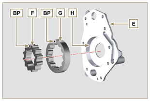
Fig 6.53
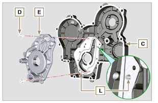
Fig 6.54 |
|
6.7.6 Timing system crankcase assembly
 Important Important
- Always replace the oil seal J after each assembly.
- Always replace the gasket P after each assembly.
- To prepare the surface of the K plane for the new application of the sealant, it must be cleaned through the use of:
- initially Loctite SF 7200
- subsequently Loctite SF 7063
Avoid any contact with the K plane and be careful not to compromise the cleaning performed.
- Lubricate the lip of the oil seal J.
- Apply a coating of Loctite 5188 around 1mm thick on the surfaces K of the crankcase C.
- Make sure that the key M (Fig. 6.56) is inserted properly on the crankshaft and that it is facing upwards.
- Check that the 2 pins N are inserted properly in the timing system crankcase C.
|
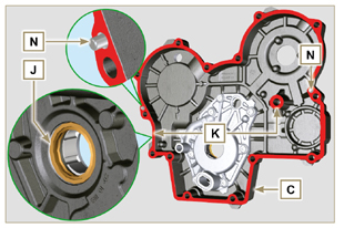
Fig 6.55 |
- Lubricate and insert the gasket P in the seat of the oil pump Q.
- Tighten the tool ST_10 on the crankshaft.
- Position the crankcase C on the base, using the reference pins N, inserting the oil pump Q on the crankshaft.
|
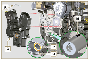
Fig 6.56 |
- Fit the timing system crankcase C with the screws R observing the indicated clamping sequence (tightening torque at 25 Nm).
|
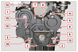
Fig 6.57 |
- Assemble sensor S by means of capscrew T on carter C inserting gasket U (tightening torque at 10 Nm ST_06).
|
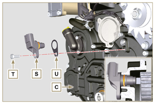
Fig 6.58 |
|
6.7.7 Crankshaft and target wheel pulley assembly
- Leave the tool ST_34 mounted (Fig. 6.44).
- Check that the pin A is mounted properly on the crankshaft Z.
- Position the pulley unit W on the crankshaft Z respecting the reference with the pin A.
- Apply Molyslip grease on the screw thread Y.
- Clamp the pulley unit W with the screw Y (tightening torque at 360 Nm).
- Remove the special tool ST_34 (Fig. 6.44).
|
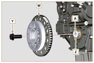
Fig 6.59 |
- Mount the bracket Z with the screws AA (tightening torque at 10 Nm).
- Perform the operations described in Par. 9.12.
- Insert the shim AB on the sensor AC.
- Clamp the sensor AC on the bracket Z with the screw AD (tightening torque at 10 Nm).
6.7.8 Coolant pump assembly
- Perform the operations described in Par 6.5.2.
|
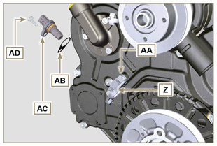
Fig 6.60 |

 Important
 Important


 Important


 Loading