
=
Search
1
General information

2
Technical information
3
Safety information
4
Storage information
5
Information regarding discharge of liquids
6
Information for replacing the functional units
7
Information for disassembly
8
Information about overhauling
9
Assembly information
10
Fluids filling information
11
Information about optional components
12
Information on adjustments
13
Tools information
14
Information about failures
15
Glossary

Timing system gear assembly and injection pump
|
9.6.1 Timing system gear assembly
 Important Important
Important
|
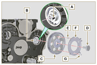 Fig 9.34 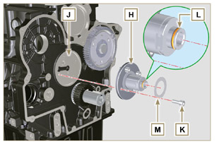 Fig 9.35 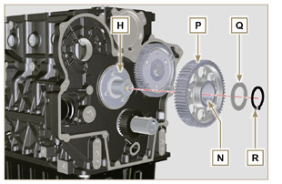 Fig 9.36 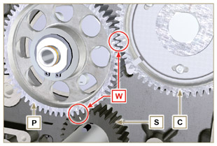 Fig 9.37 |
|
9.6.2 High-pressure injection pump
Important
|
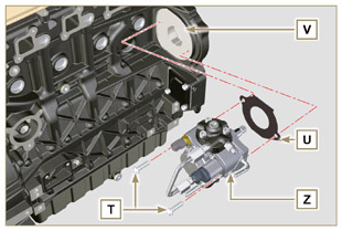 Fig 9.38 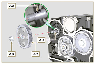 Fig 9.39 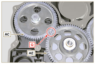 Fig 9.40 |

 Loading