9.7.1 Valve stem gasket
 Important Important
- Carry out the checks described in Par. 8.6.4 before proceeding with the following operations.
- Lubricate the oil seals A on the inside.
- Fit the oil seals A on the valve guides B using the tool ST_08.
|
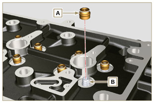
Fig 9.41 |
|
9.7.2 Electronic injector sleeves ( ) )
- Insert the seals C in the seats of the sleeve D.
- Insert the seal E with the convex side facing upward at the base of the sleeve D.
- Lubricate the gaskets C.
- Insert and carefully screw the sleeve D into the seat of the head F.
NOTE: The sleeve D must not protrude above the surface of the head BF.
- Clamp the sleeve D (tightening torque at 30 Nm).
|
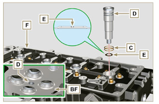
Fig 9.42 |
|
9.7.3 Electronic injectors projection
- Insert the electronic injector G inside the sleeve H.
- Mount the rocker arm pin fixing screw L up to the stop.
- Mount the electronic injector fixing bracket M and secure it with the screw N, without performing the calibration.
- Check using ST_03 tool (Fig. 9.44), the projection of the injector, which must range between 1.68 ÷ 2.42 mm.
NOTE: if the value detected does not correspond, replace gasket Q with a different thickness.
|
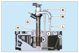
Fig 9.43
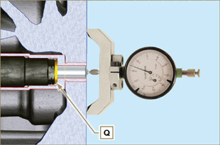
Fig 9.44 |
|
9.7.4 Valves
- Pre-lubricate and insert the valves X into the head F taking care to fit them in the original positions as per the reference marks made in Par. 7.13.4.1.
- Position the spring Y on the seat of the head F.
- Position the disk S on the spring Y centering the valve X.
- Mount the tool ST_07 on the head F fixing it on one of the holes for securing the rocker arm cover.
NOTE: Change the fixing hole according to the position of the valves to be fitted.
- Position the tool ST_07 on the valve as shown in the figure.
- Push the lever of the tool ST_07downwards, in order to lower the valve disks S in the direction of the arrow AK, and insert the valve cotters AJ inside the disk S.
- Check that the valve cotters AJ are properly mounted on the valve seats X and release the tool ST_07.
NOTE: repeat all the steps for the relevant valves and remove the tool ST_07.
|
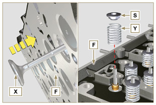
Fig 9.45 |
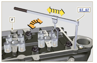
Fig 9.46 |
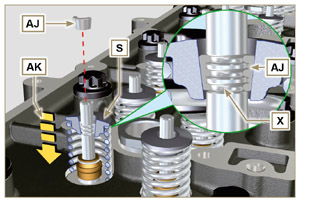
Fig 9.47 |
|
9.7.5 Cylinder head
- Fix the eyebolts AW with the screws AX onto the head F (tightening torque of 25 Nm).
- Position the piston P at the TDC.
- Position the tool ST_03 on the crankcase surface of the head and measure the piston protrusion P from head level K in 4 diametrically opposed points R. Repeat the operation for all pistons P and take note of the highest average value, determining value S (Tab. 9.2).
Tab. 9.2
| S (mm) |
Hole number |
|
0.030 - 0.126
|
1  |
|
0.127 - 0.250
|
2  |
|
0.251 - 0.375
|
3  |
- Based on the value detected at point 3, select the relevant gasket T as shown in the Tab. 9.2 (Fig. 9.50 detail U).
- Check that the crankcase surface K and the gasket T are completely free of dirt and grit.
 Important Important
- The head gasket must be replaced for each assembly.
- Position the gasket T on the surface K with reference to the centering bushings J.
|
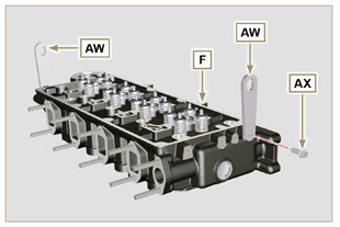
Fig 9.48
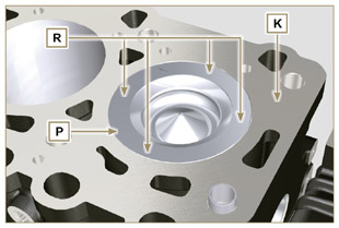
Fig 9.49
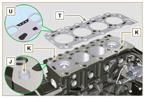
Fig 9.50 |
- Check that the surface head W is free from impurities.
- Position the head F on the crankcase Z with reference to the centering bushings J.
 Important Important
- The fastening bolts V must be replaced every time they are assembled.
- Secure the head F by tightening the screws V strictly following the sequence indicated in the Fig. 9.52 or Fig. 9.53 and the tightening torque indicated in the Tab. 9.3.
|
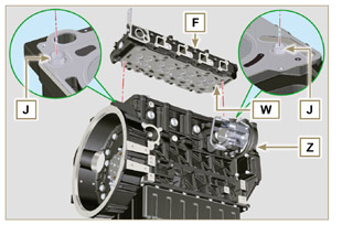
Fig 9.51 |
 Important Important
- Failure to adhere to the bolt fixing procedures may compromise the functionality of the engine, and also may cause damage to persons and property.
- Tighten capscrews V observing the cycles, tightening, and subsequent rotation as indicated inTab. 9.3.
- For engine KDI 1903 TCR: 8 screws Torx M12x1,25 (Fig. 9.52).
- For engine KDI 2504 TCR: 10 screws Torx M12x1,25 (Fig. 9.53).
|
3 CYLINDERS
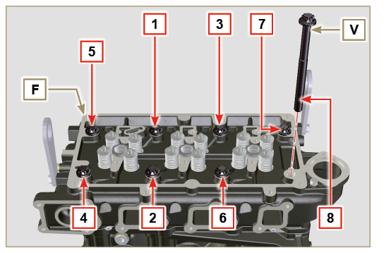
Fig 9.52
|
Tab. 9.3
| CYCLE |
TORQUE |
| 1 |
40 Nm |
| 2 |
70 Nm |
| 3 |
100 Nm |
| 4 |
90° |
| 5 |
90° |
| 6 |
90° |
|
4 CYLINDERS
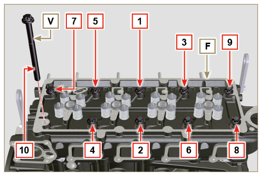
Fig 9.53
|
|
9.7.6 Rods and valve bridges
- Insert the rocker control rods AA into the niches of the head F.
 Important Important
- Properly centre the rods AA into the spherical housing of the camshaft tappets AB.
- Mount the valve bridge AC on to the pairs of discharge and suction valves.
|
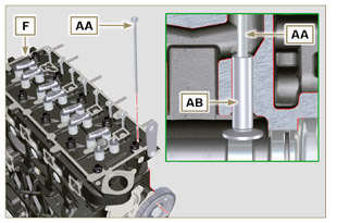
Fig 9.54 |
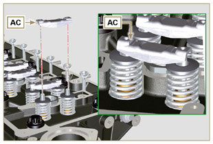
Fig 9.55 |
|
9.7.7 Rocker arms
 Important Important
- To correctly position the rocker arms, turn the rocker arm pin AH with the lower height AL towards the timing system side as in Fig.9.57.
- The discharge rocker arm AT is shorter than the suction arm AR.
- Fit the lock ring AM into the seat AN of the rocker arm pin AH.
- Position the pin AH with the screw support surface AP facing upwards and insert the 2 shoulder rings AQ.
- Insert in sequence the suction rocker arm AR, the holder AS and the discharge rocker arm AT in the pin AH.
- Insert the spring AU in the pin AH.
- Repeat points 3, 4 for all the rocker arms.
NOTE: The holder AV must be fitted with the last pair of rocker arms towards the flywheel.
- Insert 2 shoulder rings AQ and the lock ring AN to lock all the components inserted in the pin AH.
NOTE: The spring AU ensures that the supports AS and AV are kept in place.
|
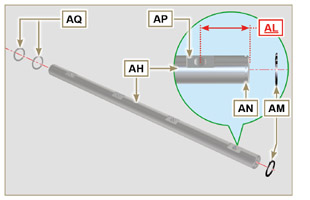
Fig 9.57
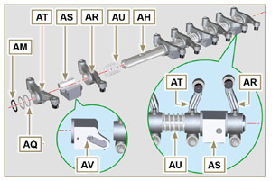
Fig 9.58 |
|
9.7.8 Rocker arm pin assembly
 Important Important
- Position the rocker arm pin assembly BB on a level to align all the support surfaces.
- Check that the pistons are positioned half way between the TDC and BDC. Rotate the crankshaft 90° counterclockwise with regard to the 1st cylinder TDC, positioning the crankshaft pin BP as shown in Fig 9.60a. If the crankshaft pulley and the timing gear cover have not been removed, rotate the
crankshaft positioning the reference BQ located on the target wheel in correspondence of the speed sensor, as shown in Fig. 9.60b.
- If the engine is painted or protected with clear paint, replace the fastening screws BE.
- Position the rocker arm pin assembly BB on the head F, respecting the plug BC on the head using the holder indicated AV.
- Check the correct positioning of all the rocker arms and the u-bolt control valves (detail BD). House the tappet in the seat of the rocker arms control rod.
- Secure the rocker arm pin BB tightening the screws BE (tightening torque to 25 Nm). Adhere to the screw tightening sequence BE as shown in Fig. 9.60.
|
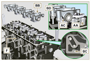
Fig 9.59
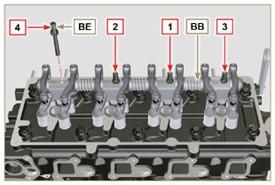
Fig 9.60 |
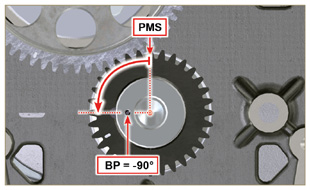
Fig 9.60a |
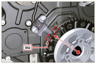
Fig 9.60b |
|
9.7.9 Assembly Rocker arm cover
 Important Important
- Replace gasket BF, BL and BM with each assembly (ST_11 - ST_12).
Modified component, see service letter 700027.
- Observe the order of tightening illustrated in Fig. 9.62 - 9.63.
- Position tool ST_17 onto the head in correspondence with the two fastening holes 5 and 6.
- Position gasket BF on cylinder head F using tool ST_17 as a guide.
- With vaseline lubricate the gaskets BL in the upper part, and the gaskets BM in the lower part.
- Attach the rocker arm cover BN on the head F with the screw BG (tightening torque to 10 Nm).
|
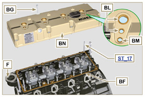
Fig 9.61 |
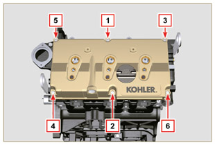
Fig 9.62 |
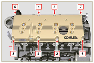
Fig 9.63 |

 Important


 Important


 Important
 Important
 Important

 Important

 Important


 Important


 )
)


 Loading