=
Search
1
General information

2
Technical information

Important The engine may be damaged if operated with improper oil level. Do not exceed the MAX level because a sudden increase in engine rpm could be caused by its combustion. Use only the recommended oil to ensure adequate protection, efficiency and service life of the engine. The use of lubricants other than recommended may shorten the engine life. Viscosity must be appropriate to the ambient temperature to which the engine is to be exposed. Danger Prolonged skin contact with the exhausted engine oil can cause cancer of the skin. If contact with oil cannot be avoided, thoroughly wash your hands with soap and water as soon as possible. For the exhausted oil disposal, refer to the Par. DISPOSAL and SCRAPPING. 2.4.1 SAE oil classification In the SAE classification, oils are identified according to viscosity without considering any other qualitative characteristic. The code is composed of two numbers, which indicate, and must correspond to, the ambient temperature in which the engine operates, the first number refers to the viscosity when cold, for use during winter ("W"), while the second number is for viscosity at high temperatures. 2.2 RECCOMENDED OIL TCR STAGE-V (*1) (*2) TCR TIER IV FINAL (*1) TCR/D TIER III o NON CERTIFICATO (*3) WITH SPECIFICATIONS API CJ-4 Low S.A.P.S CK-4 Low S.A.P.S CJ-4 Low S.A.P.S CK-4 Low S.A.P.S CI-4 Plus CI-4 CH-4 ACEA E6 Low S.A.P.S. E6 Low S.A.P.S. E7 E4 VISCOSITY SAE 10w-30 (-25°c ÷ +40°C)10w-40 (-25°C ÷ +50°C)5w-30 (-30°c ÷ +40°C)5w-40 (-30°c ÷ +50°C)0w-40 (-40°c ÷ +50°C) 10w-30 (-25°c ÷ +40°C)10w-40 (-25°C ÷ +50°C)5w-30 (-30°c ÷ +40°C)5w-40 (-30°c ÷ +50°C)0w-40 (-40°c ÷ +50°C) 10w-30 (-25°c ÷ +40°C)10w-40 (-25°C ÷ +50°C)5w-30 (-30°c ÷ +40°C)5w-40 (-30°c ÷ +50°C)0w-40 (-40°c ÷ +50°C) Low S.A.P.S. technology (oil with low Sulfated Ash, Phosphorus, Sulfur content) keeps catalyst in good working conditions. The presence of sulfated ash, phosphorus and sulfur causes with time the catalyst clogging and its consequent inefficiency. For Mid S.A.P.S oil sequence the sulfated ash level is the same as API CJ-4 ≤ 1.0% but as per ACEA standardization those oils are referenced as mid SAPS. Filtration of oils is critical to proper operation and lubrication; always change filters regularly as specified in this manual. (*1) NOTA: Do NOT use fuel with sulphur content above 15ppm. (*2) - On all engines compliant with Stage-V emission regulation (engines with DPF device), the oil to use must comply with the specification API CJ-4 Low S.A.P.S or ACEA E6 Low S.A.P.S. (*3) - NOTE: Do NOT use fuel with sulphur content above 500ppm. (*3) - NOTE: Low S.A.P.S. oils, sulfate ashes <1% may not be used with fuels with a sulfur content >50ppm.
Important Use of other types of fuel could damage the engine. Do not use dirty diesel fuel or mixtures of diesel fuel and water since this will cause serious engine faults. Any failures resulting from the use of fuels other than recommended will not be warranted. Warning Clean fuel prevents the fuel injectors from clogging. Immediately clean up any spillage during refuelling. Never store diesel fuel in galvanized containers (i.e. coated with zinc). Diesel fuel and the galvanized coating react chemically to each other, producing flaking that quickly clogs filters or causes fuel pump and/or injector failure. 2.3 FUEL COMPATIBILITY EN 590 (biodiesel content max. 7% (V/V)) ASTM D 975 Grade 1-D S15 ASTM D 975 Grade 2-D S15 NATO F-54, equivalent to diesel fuel in accordance with EN 590 EN 590 or ASTM D 975 Grade 1, 2 -D S15 Arctic Diesel JIS K 2204 No. 1, No. 2 NOTE: In a warranty case the customer must prove by a certificate from the fuel supplier that an allowed fuel was used. KDI Electronic Injection Tier 4 final – Stage IIIB – Stage IV- Stage V certified Engines Those engines are designed for fuels in accordance with EN 590 and ASTM D975 for a cetane number of at least 45. Since those engines are equipped with exhaust gas after-treatment such as Diesel Oxidation Catalyst (DOC), Diesel Particulate Filter (DPF), Selective Catalytic Reduction (SCR), they may only be operated with sulfur-free diesel fuels (EN 590, DIN 5168, ASTM D975 Grade 2-D S15, ASTM D975 Grade 1-D S15). Otherwise, compliance with the emission requirements and durability are not guaranteed.Insufficient lubricating capacity can lead to serious wear problems above all in common rail injection systems. Too low a lubricating capacity is particularly a problem in fuels with a low sulfur content (and in this respect sulfur contents ‹500 mg/kg can already be considered low). An adequate lubricating capacity is guaranteed by the appropriate additives in low-sulfur (‹50 mg/kg) or sulfur-free (‹10 mg/kg or ‹15 mg/kg) diesel fuels according to EN 590 and ASTM D 975. In low-sulpur and sulfur-free diesel fuels which do not comply with this standard, the lubricating capacity may have to be guaranteed by additives. The parameter for sufficient lubricating capacity is a maximum wear spot of 460 micrometers in the HFRR test (EN ISO 12156-1). KDI Electronic Injection Tier 3 – Stage IIIA emission equivalent certified Engines (EGR engines) Those engines are designed for fuels in accordance with EN 590 and ASTM D975 for a cetane number of at least 45. Since those engines are not equipped with exhaust gas after-treatment, they can be operated with diesel fuels with sulfur content up to 500 mg/kg (ppm). Compliance with the emission requirements is guaranteed only with sulfur content up to 350 mg/kg (ppm).Fuels with a sulfur content > 50 mg/kg demand a shorter lubricating oil change interval. This is set at 250hrs. However, the engine oil must be changed when the Total Base Number TBN is reduced to 6.0 mgKOH/g test method ASTM D4739. Do not use low SAPS engine oils. KDI Electronic Injection uncertified Engines (no EGR engines) Those engines are designed for fuels in accordance with EN 590 and ASTM D975 for a cetane number of at least 45. Since those engines are not equipped with exhaust gas after-treatment, they can be operated with diesel fuels with sulfur content up to 2000 mg/kg (ppm). Fuels with a sulfur content > 15 mg/kg demand a shorter lubricating oil change interval. This is set at 250hrs. However, the engine oil must be changed when the Total Base Number TBN is reduced to 6.0 mgKOH/g test method ASTM D4739. 2.5.1 Fuel for low temperatures When operating the engine in ambient temperatures lower than 0 degrees C, use suitable low temperature fuel normally available from fuel distributors and corresponding to the specifications of Tab. 2.3. These fuels reduce the formation of paraffin in diesel at low temperatures. When paraffin forms in the diesel, the fuel filter becomes blocked interrupting the flow of fuel. 2.5.2 Biodiesel fuel Fuels containing 10% methyl ester or B10, are suitable for use in this engine provided that they meet the specifications listed in the Tab. 2.3. DO NOT USE vegetable oil as a biofuel for this engine. 2.4 BIODIESEL COMPATIBILITY Biodiesel according to EN 14214 (only permissible for mixture with diesel fuel at max. 10% (V/V)) US biodiesel according to ASTM D6751 – 09a (B100) (only permissible for mixtures with diesel fuel at 10% (V/V)) 2.5.3 Synthetic fuels: GTL, CTL, BTL, HVIt is a well-known fact that engines which are operated for longer periods with conventional diesel fuel and then converted to synthetic fuels suffer shrinkage of polymer seals in the injection system and thus fuel leaks. The reason for this behavior is that the aromatic-free synthetic fuels can lead to a change in the sealing behavior of polymer seals.Therefore, conversion from diesel fuel to synthetic fuel may only be done after changing the critical seals. The problem of shrinkage does not occur when an engine was operated with synthetic fuel from the start. 2.5.4 Non-Road Fuels Only for KDI De- Contented Electronic Injection Tier 3 – Stage IIIA emission equivalent certified Engines (EGR engines) and KDI De- Contented Electronic Injection Uncertified Engines (no EGR engines). Other non-road fuels may be used if they comply with all the limit values of EN 590 except for the fuel density, the cetane number and the sulfur content. The following limits apply for these parameters: 2.5 FUEL PARAMETER UNIT LIMIT VALUE Cetane number Min. 49 Fuel density at 15°C Kg/m3 820 - 860 Sulfur content mg/kg or ppm max. 500 2.5.5 Jet FuelsOnly for KDI De- Contented Electronic Injection Uncertified Engines (no EGR engines).The following jet fuels can be used but only adopting an additional fuel filter with lubricity doser: 2.6 FUEL F-34/F-35 (kerosene, NATO designation) JP-8 (kerosene, US military designation) F-44 (kerosene, NATO designation JP-5 (kerosene, US military designation) F-63 (kerosene, NATO designation, equivalent to F-34/F-35 with additives) Jet A (kerosene for civil aviation) F-65 (kerosene, NATO designation, 1:1 mixture of F-54 and F-34/F-35) Jet A1 (kerosene for civil aviation) 2.5.6 Emission-Related Installation InstructionsFailing to follow the instructions in the applications guidebook when installing a certified engine in a piece of nonroad equipment violates federal law (40 CFR 1068.105(b)), subject to fines or other penalties as described in the Clean Air Act.OEM must apply a separate label with the following statement: “ULTRA LOW SULFUR FUEL ONLY” near the fuel inlet.Ensure you are installing an engine appropriately certified for your application. Constant speed engines may only be installed on constant speed equipment for constant speed operation.If you install the engine in a way that makes the engine's emission control information label hard to read during normal engine maintenance, you must place a duplicate label on the equipment, as described in 40 CFR 1068.105.
Battery not supplied by Kohler Tab. 2.7 RECOMMENDED BATTERIES AMBIENT TEMPERATURE BATTERY TYPE ≥ - 15°C 100 Ah - 800 CCA/SAE < -15°C 120 Ah - 1000 CCA/SAE
3
Safety information

4
Storage information

5
Information regarding discharge of liquids

6
Information for replacing the functional units

7
Information for disassembly

8
Information about overhauling

9
Assembly information

10
Fluids filling information

11
Information about optional components

12
Information on adjustments

13
Tools information

14
Information about failures

15
Glossary


4th PTO (replacement)
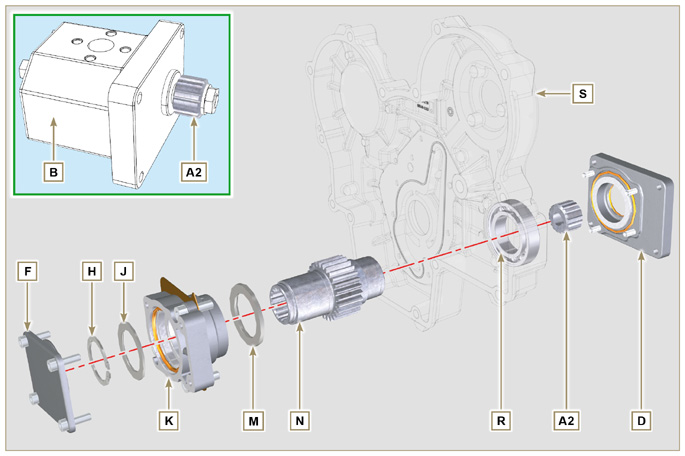 Fig 11.21 |
|
|
|
|
11.7.1 Disassembly
|
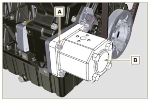 Fig 11.22 |
|
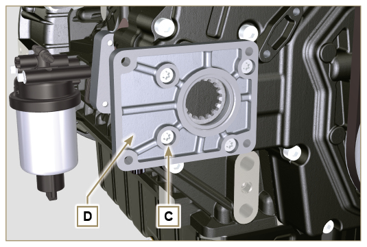 Fig 11.23 |
|
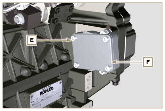 Fig 11.24 |
|
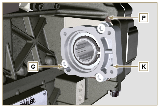 Fig 11.25 |
|
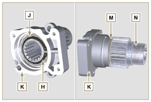 Fig 11.26 |
|
11..2 Assembly
 Important Important
|
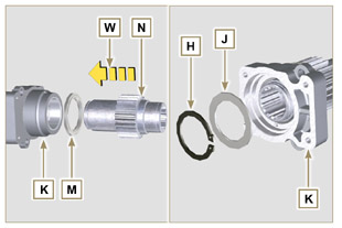 Fig 11.27 |
 Important Important
|
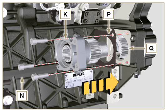 Fig 11.28 |
 Important Important
|
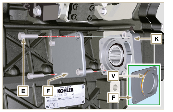 Fig 11.29 |
 Important Important
|
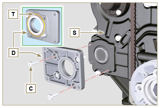 Fig 11.30 |
 Important Important
|
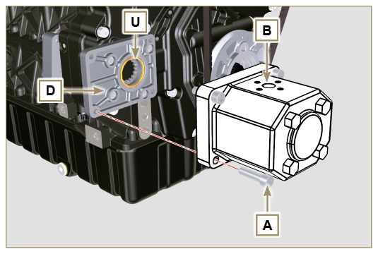 Fig 11.31 |


 Loading