 Danger Danger
- Highly carcinogenic material!
- The dust contained inside the DPF is particularly fine and therefore classified as highly dangerous to living beings.
- Before proceeding to any operation, wear:
dust mask
gloves
goggles
- Do not allow any other operator who is not equipped with the above mentioned protective equipment to approach.
|
|
- Obtain a new replacement KIT for the DPF filter or a replacement KIT with regenerated DPF filter from your spare parts service.
 Important Important
- Before disassembling/assembling any sensors, see Par. 2.17.5 and 2.17.6
- See service letter 710023.
- Always replace the seal P upon every assembly.
- During disassembly, do not expose the DPF to the surrounding environment for a long time and store it in a sealed bag as soon as possible.
- During disassembly operations, avoid using electric screwdrivers as vibrations could release the dust inside the DPF
- Do not try to clean the DPF
- Do not blow with compressed air
- Do not release the DPF or the dust contained in it in the environment
- Dispose of the DPF only in authorised centres
- Perform the operations indicated in point 1 of Par. 11.8.
- Open the package of the DPF replacement KIT, taking care not to damage it.
- Unscrew screw A and loosen clamps B, then remove the Delta-P sensor D.
- Disconnect pipes C from their unions J and remove the Delta-P sensor D.
- Unscrew and remove unions J.
|
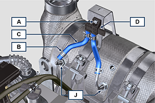
Fig. 11.19
|
- Loosen clamps E and remove manifold N.
|
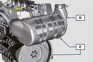
Fig. 11.20
|
- Loosen clamp G and remove the DPF filter H.
NOTE: do not remove clamp G.
- Inspect the DPF filter to detect any visible signs of oil contamination.
- Put the removed DPF filter in the plastic container supplied with the replacement KIT and send it to your spare parts service using the replacement KIT package.
NOTE: a residual value will be recognised depending on whether the used DPF is intact and recyclable or damaged and requiring a correct disposal.
|
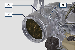
Fig. 11.21
|
- Loosen the clamps Q and S and remove the manifold with DOC M from the flexible hose R.
|
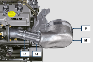
Fig. 11.22
|
- Fit the new manifold with the DOC filter M on the support T, inserting the flexible hose R inside the inlet of the manifold M.
|
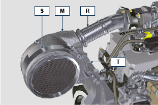
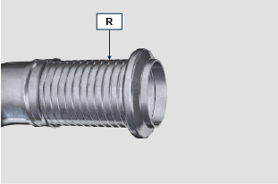
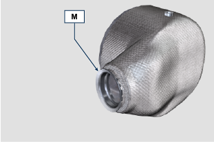
Fig. 11.23
|
 Important Important
- Do not apply any tension during the assembly of components.
- Before fastening the manifold M, it must be oriented in the same position as the previously installed DOC filter.
- Tighten the clamp Q (tightening torque of 10 Nm).
- Tighten the clamp S (tightening torque of 12 Nm).
|

Fig. 11.24
|
- Insert the gasket P on the manifold with DOC filter M.
- Insert the new DPF filter H inside clamp G.
- Insert the DPF filter H on manifold M until reaching the gasket P.
|
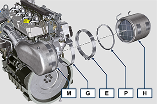
Fig. 11.25
|
 Important Important
- Before fastening the DPF filter H, it must be oriented in the same position as the previous filter.
- Do not apply any tension during the assembly of components.
- Fasten the DPF filter H with clamp E (tightening torque 12 Nm).
|
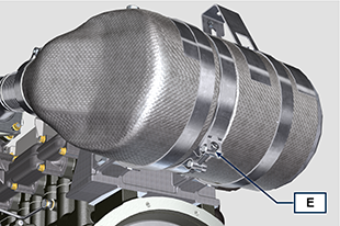
Fig. 11.26
|
- Insert gasket P on the DPF filter H.
- Insert manifold N on the DPF filter H until reaching the gasket P.
 Important Important
- Before fastening manifold N, it must be oriented in the original position.
- Fasten manifold N with clamp E (tightening torque 12 Nm).
|
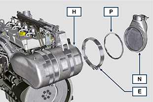
Fig. 11.27
|
- Position support K in contact with support K1 and fasten clamp G (tightening torque 12 Nm).
|
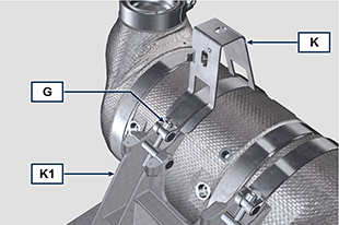
Fig. 11.28
|
- Screw unions J on the DPF filter H and position them about 20° away from the centre line (as in Fig. 11.30).
|
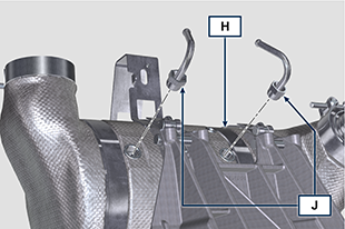
Fig. 11.29
|
- Fix unions J (tightening torque see service letter 710015).
|
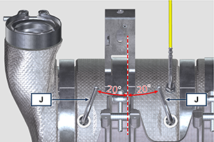
Fig. 11.30
|
- Fit pipes C on unions J and fasten them with clamps B.
- Fix the Delta-P sensor D on its support K by means of screw A (tightening torque 10 Nm).
- Provide the machine owner with the warranty certificate of the new DPF filter KIT installed.
- Perform the "DPF replacement" procedure to reset the ASH & SOOT through the relevant KOHLER diagnostic tool interfaced with the ECU.
|
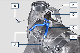
Fig. 11.31
|

 Important
 Important
 Important
 Important


 Loading