
=
Search
1
General information

2
Technical information
3
Safety information
4
Storage information
5
Information regarding discharge of liquids
6
Information for replacing the functional units
7
Information for disassembly
8
Information about overhauling
9
Assembly information
10
Fluids filling information
11
Information about optional components
12
Information on adjustments
13
Tools information
14
Information about failures
15
Glossary

Cooling circuit
|
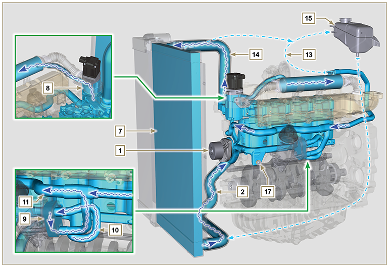
2.11.1 Cooling circuit diagram
Tab 2.25
|
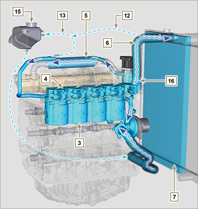 Fig 2.21 |
||||||||||||||||||||||||||||||||||||
|
|
|||||||||||||||||||||||||||||||||||||
| 2.11.2 Water pump Tab 2.26
|
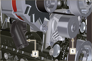 Fig 2.23 |
||||||||||||||||||||||||
| 2.11.3 Thermostatic valve Tab 2.27
Starting opening temperature of +83 °C (0/-3 °C). |
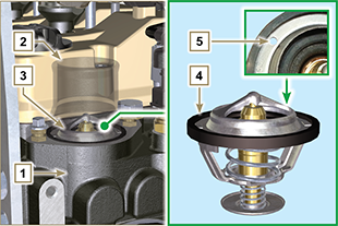 Fig 2.24 |
||||||||||||||||||||||||
|
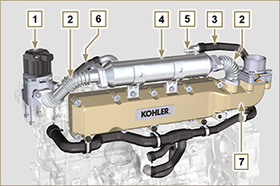
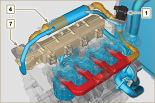
2.11.4 EGR gas circuit cooling (EGR Cooler) Device that cools exhaust gas
Tab 2.28
Tab 2.29
|
Fig 2.25
Fig 2.25a |

 Loading