|
2.12.1 Turbocharger
The turbocharger is controlled by means of exhaust gas that activates the turbine.
 Important Important
Tab 2.30
| POS. |
DESCRIPTION |
| 1 |
Air intake hose |
| 2 |
Air compression volute |
| 3 |
Turbo charger central body |
| 4 |
Turbine housing with Waste Gate valve |
| 5 |
Gas exhaust flange |
| 6 |
Waste Gate control valve hose |
| 7 |
Waste Gate valve control actuator |
| 8 |
Waste Gate control valve linkage |
| 9 |
Air compressed flow hose to intercooler |
| 10 |
Oil drain pipe |
| 11 |
Turbo charger lubrication pipe |
|
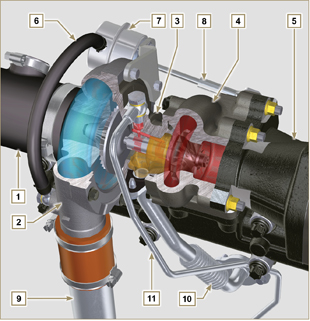
Fig 2.26 |
|
2.12.2 Intake and exhaust circuit diagram with EGR
| |
Air in intake |
|
Gas in recycle |
|
Gas in exhaust |
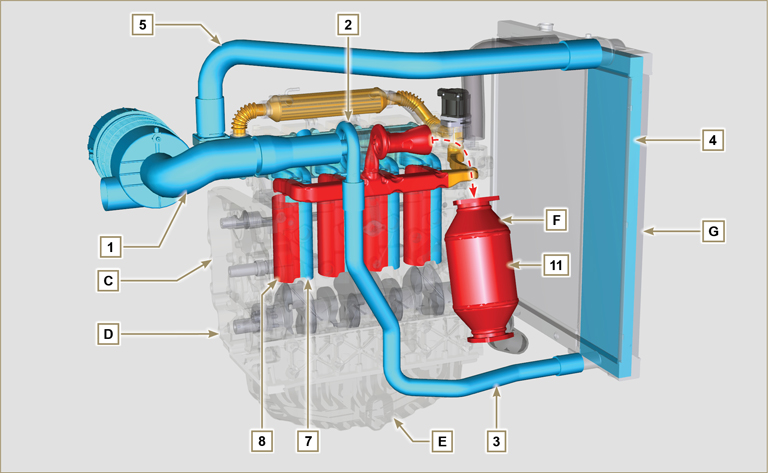
Fig 2.27a
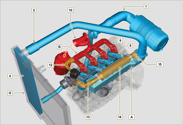
Fig 2.27b
 Important Important
- The air temperature inside the intake manifold must never exceed that of the environment by 10°C.
Filtered air is sucked by the turbocharger, which compresses and sends it to the intercooler (as a consequence of compression, the air increases the temperature - the Intercooler cools it - this process enables better performance during combustion inside the cylinders). From the Intercooler, it is sent to the
intake manifold and, via ducts in the cylinder head, enters the cylinders. Compressed air inside the cylinders and mixed with the fuel transforms into Gas after combustion. The gas is expelled from the cylinders and sent to the exhaust manifold. The exhaust manifold sends the Gases to 2 ducts:
- 1st duct: to the turbocharger body (the expelled Gases activate the turbine), the Gases then proceed towards the catalyst, which break down the pollutants contained in them before being definitely expelled.
- 2nd duct: to the EGR circuit, which takes care of recovering a part of the Gases that return to intake
(this process burns less oxygen when power is not requested, thus breaking down pollutants further).
The EGR circuit is managed by ECU, which controls the EGR valve that provides for the recovery of Gases when the engine does not require power.
The EGR circuit is furnished with a heat exchanger (EGR Cooler), which cools the recovered Gases (this process enables better performance during combustion inside the cylinders).
Tab 2.31a
| POS. |
DESCRIPTION |
| 1 |
Air in intake from air filter |
| 2 |
Air in compression |
| 3 |
Air in intercooler flow |
| 4 |
Air cooling |
| 5 |
Air in intake manifold flow |
| 6 |
Air in head intake |
| 7 |
Air in cylinder intake |
| 8 |
Gas in cylinder outlet |
| 9 |
Gas in head outlet |
| 10 |
Gas in outlet towards catalyst |
| 11 |
Gas in oxidation |
| 12 |
Gas in recycle towards EGR valve |
| 13 |
Gas in EGR valve outlet |
| 14 |
Gas cooling (in EGR Cooler) |
| 15 |
Exhaust gas recirculation into intake manifold |
| A |
Intake manifold |
| B |
Exhaust manifold |
| C |
Upper crankcase |
| D |
Lower crankcase |
| E |
Oil sump |
| F |
DOC |
| G |
Radiator/intercooler |
|
2.12.3 ATS Device (optional)
2.12.3.1 DOC
The catalyst is a device to filter exhaust gas by means of its oxidation.
Internally, it is composed of hundreds of small ducts that enable the passage of exhaust gas.
It contains precious metals (platinum, palladium, iridium).
NOTE: The image is indicative only. The installation of the DOC must be approved by KOHLER, for each application.
In order to prevent breakage on the connection flange, the catalyst is normally connected via a hose.
 Important Important
- In order to prevent breakage on the connection flange, the DOC must be connected via a flexible exhaust tube (POS. 14 - Tab. 2.31b).
Tab 2.31b
| POS. |
DESCRIPTION |
| 4 |
Turbocharger |
| 5 |
Gas exhaust flange |
| 13 |
DOC |
| 14 |
Flexible exhaust tube |
|
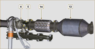
Fig 2.28a |
2.12.3.1.1 DOC exhaust gas path and transformation
NOTE: The following data are indicative and may vary based on the engine use conditions.
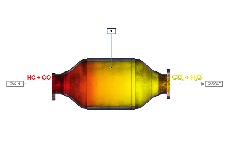
Fig 2.28b
Tab 2.31c
| POS. |
DESCRIPTION |
| 1 |
DOC Element |
| HC |
Unburnt hydrocarbons |
| CO |
Carbon monoxide |
| CO2 |
Carbon dioxide |
| H2O |
Water |
|
|
2.12.3.2 DOC+DPF
The DOC+DPF system reduces emissions because the DPF eliminates the particulate generated by Diesel fuel combustion. The system triggers automatic DPF regeneration cycles depending on the degree of clogging.
The smell of the gases out of the exhaust line is different than the traditional one of gases from Diesel engines. Moreover, during regeneration stages, the exhaust gases could temporarily be white.
NOTE: During regeneration, engine idling will increase.
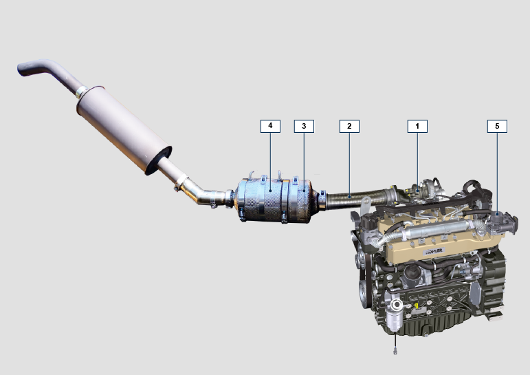
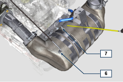 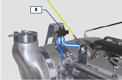
Fig 2.30a
Tab 2.31f
| POS. |
DESCRIPTION |
| 1 |
turbocharger |
| 2 |
exhaust pipe from turbine |
| 3 |
DOC |
| 4 |
DPF |
| 5 |
ETB |
| 6 |
EGTS Black |
| 7 |
EGTS Yellow |
| 8 |
Delta-P (Delta Pressure) |
|
|
2.12.3.2.1 DPF regeneration strategy
You can intervene on the machine control panel for the DPF regeneration operations "only if requested by means of specific warning lights or messages on the control panel".
Tab. 2.31g describes the level of particulate accumulation, the relationship with the warning lights that will light up on the panel, the performance limitations of the engine and the operator’s options intervention.
Forced regeneration must be executed in accordance with the machine instructions.
Tab 2.31g
| SOOT LEVEL |
WARNING LAMPS *1 |
ENGINE DE-RATE |
OPERATOR POSSIBLE ACTIONS |
OPERATING CONDITIONS |
| Level 0 |
|
|
|
|
| Level 1 |
| Level 2 |
| Level 3 |

Fixed
|
Forced Regeneration is Necessary |
- Coolant temperature at 60 °C
- Do not switch the engine off
- Stationary vehicle
- No load applied to the engine *2
|
| Level 4 |

Flashing
|
Engine de-rate |
Forced Regeneration is Necessary |
- Coolant temperature at 60 °C
- Do not switch the engine off
- Stationary vehicle
- No load applied to the engine *2
|
| Level 5 |

Flashing
|
Strong Engine de-rate |
Contact an authorized KOHLER workshop.
Service Regeneration Required
|
REGENERATION via KOHLER software
|
*1: The warning lights be different – consult the machine manual.
*2: Unless stated otherwise in the machine manual.
 Warning Warning
- Forced regenerations must only be executed if required by the ECU when the "HIGH SOOT" warning light goes on (due to a Level 3 - 5 particulate accumulation).
- Do NOT execute the forced regenerations if not required by the ECU (due to a Level 0 - 2 particulate accumulation).
- The minimum engine speed increases during the forced regeneration phases.
- Repeated forced regenerations cause significant engine oil contamination by the fuel.
- The oil level check must be executed after every forced regeneration.
- If the regeneration inhibition function is misused, the particulate accumulation level will increase within a short time.
- The engine oil filter and oil must be changed after a Service Regeneration is completed via KOHLER software
- (Level 5 Particulate accumulation).
- Fuel contamination allowed in the engine oil is 3% MAX.
- Any engine load must be eliminated during forced regeneration so as to prevent damaging the ATS *2 system.
- Do not switch the engine off during level 3, 4 and 5 regeneration so as to prevent damaging the ATS system.
|
|
2.12.3.2.2 DOC+DPF exhaust gas path and transformation
NOTE: The following data are indicative and may vary based on the engine use conditions.
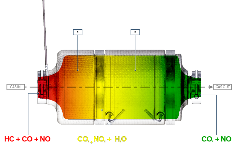
Fig 2.30b
Tab 2.31h
| POS. |
DESCRIPTION |
| 1 |
DOC Element |
| 2 |
DPF filter (particulate accumulation) |
| HC |
Unburnt hydrocarbons |
| CO |
Carbon monoxide |
| CO2 |
Carbon dioxide |
| NO2 |
Nitrogen dioxide |
| NO |
Nitrogen oxide |
| H2O |
Water |
|
|
2.12.3.2.3 Intake and exhaust circuit diagram with DOC+DPF
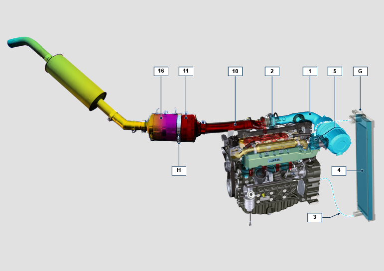
Fig 2.30c
Tab 2.31i
| POS. |
DESCRIPTION (pos. For DPF components only) |
| 1 |
Air in intake from air filter |
| 2 |
Air in compression |
| 3 |
Air in intercooler flow |
| 4 |
Air cooling |
| 5 |
ETB |
| 10 |
Gas in outlet towards DOC |
| 11 |
Gas in oxidation (DOC) |
| 16 |
Particulate elimination (DPF) |
| G |
Radiator/intercooler |
| H |
ATS |
|
|
2.12.3 Air filter (optional)
NOTE: Component not necessarily supplied by KOHLER.
 Important Important
- The air filter is a dry type of filter with a paper filtering element; elements H and L are replaceable (refer to Tab. 2.8 and Tab.2.9 for procedure frequency on components).
- Filter suction must be positioned in a cool place.
- Should a hose be used, the length must not exceed 400 mm and is to be as straight as possible.

Fig 2.31
|
Tab 2.32
| POS. |
DESCRIPTION |
| H |
Air filter cartridge |
| L |
Air filter safety cartridge |
| M |
Filter cover |
| N |
Filter support |
| Q |
Dust exhaust valve |
| R |
Filter cover hook |
|

 Important
 Important
 Important
 Warning
 Important


 Loading