
=
Search
1
General information

2
Technical information
3
Safety information
4
Storage information
5
Information regarding discharge of liquids
6
Information for replacing the functional units
7
Information for disassembly
8
Information about overhauling
9
Assembly information
10
Fluids filling information
11
Information about optional components
12
Information on adjustments
13
Tools information
14
Information about failures
15
Glossary

Electric system
|
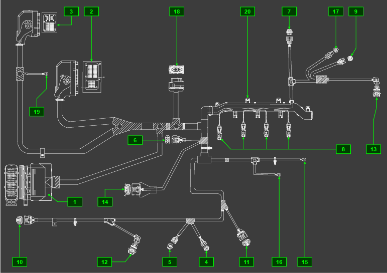
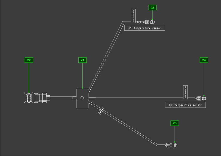
2.13.1ECU (and DCU for SCR versions only) input and output signals diagram
|
||||||||||||||||||||||||||||||||||||||||
|
2.13.2 Control unit (ECU)
 Important Important
|
2.13.2.1 Installation rules
|
|||||||||||||||||||||||||||||||||||||||
|
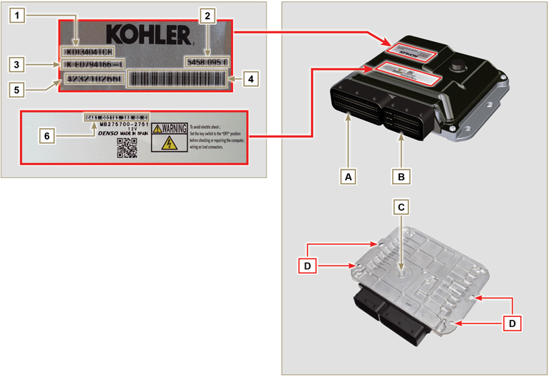
Fig 2.32 - Fig. 2.33
Tab. 2.33
|
||||||||||||||||||||||||||||||||||||||||
|
||||||||||||||||||||||||||||||||||||||||
|
Tab. 2.34
|
 Fig 2.34a 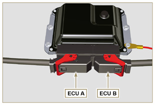 Fig 2.34b |
||||||||||||||||||||||||||||||||||||||||||||||||||||
|
NOTE: Click by side to play the procedure. |
|||||||||||||||||||||||||||||||||||||||||||||||||||||
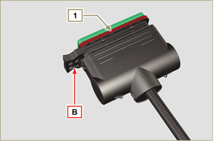
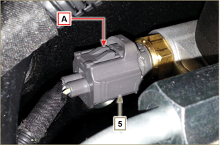
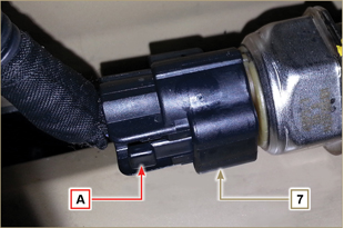
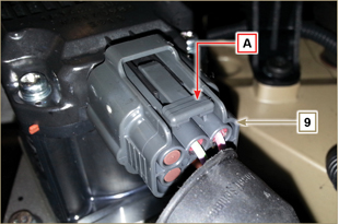
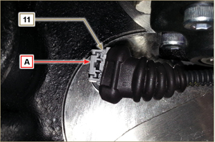
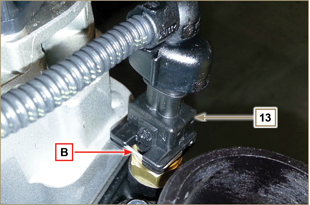
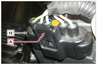
| 2.13.3.1 Wiring disconnection All sensor connectors and electronic control devices are sealed. The connectors must be disconnected by means of pressure on tabs A or unblock the retainers B, as illustrated from Fig. 2.34c to Fig. 2.34q. |
|
||||||||||||||||||||||||||||||||||||||||||||||||||||
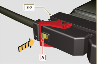 Fig 2.34d |
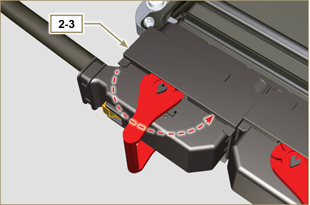 Fig 2.34e |
||||||||||||||||||||||||||||||||||||||||||||||||||||
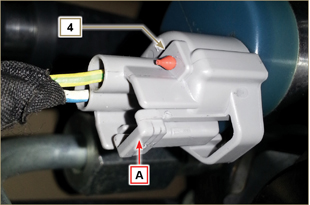 Fig 2.34f |
Fig 2.34g |
||||||||||||||||||||||||||||||||||||||||||||||||||||
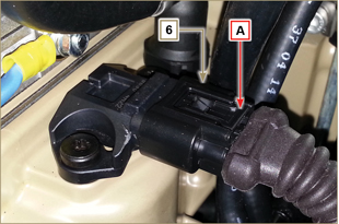 Fig 2.34h |
Fig 2.34i |
||||||||||||||||||||||||||||||||||||||||||||||||||||
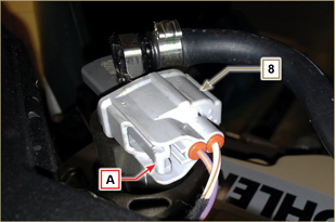 Fig 2.34l |
Fig 2.34m |
||||||||||||||||||||||||||||||||||||||||||||||||||||
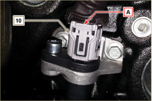 Fig 2.34n |
Fig 2.34o |
||||||||||||||||||||||||||||||||||||||||||||||||||||
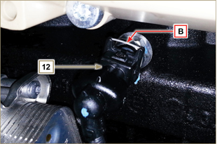 Fig 2.34p |
Fig 2.34q |
||||||||||||||||||||||||||||||||||||||||||||||||||||
|
Fig 2.34r |

 Loading