
1
General information

2
Technical information
3
Safety information
4
Storage information
5
Information regarding discharge of liquids
6
Information for replacing the functional units
7
Information for disassembly
8
Information about overhauling
9
Assembly information
10
Fluids filling information
11
Information about optional components
12
Information on adjustments
13
Tools information
14
Information about failures
15
Glossary

Sensors and switches
|
2.14.1 Revolution sensor on target wheel
The sensor produces a 5V square wave signal having a Hall effect while the crankshaft in rotation detects its position and speed. The data sent by this sensor enables the ECU to pilot fuel anticipation injection for each piston.
|
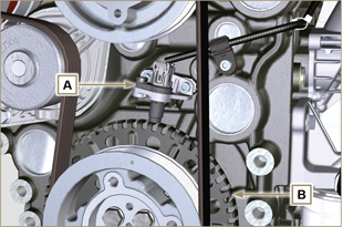 Fig 2.35 |
||||||||||||||||||||||||||||||||||||||||
|
2.14.2 Camshaft sensor |
 Fig 2.36 |
||||||||||||||||||||||||||||||||||||||||
|
2.14.3 T-MAP sensor
The T-MAP F sensor is situated on the intake manifold.
NOTE: R indicates the pin where it is possible to measure electrical resistance.
|
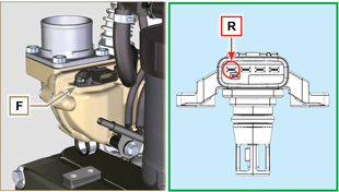 Fig 2.37 |
||||||||||||||||||||||||||||||||||||||||
|
2.14.4 Common Rail pressure sensor
 Important Important
|
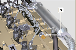 Fig 2.38 |
||||||||||||||||||||||||||||||||||||||||
|
2.14.5 Fuel filter water detection sensor The butterfly valve nut M situated in the lower part of the body sensor enables the elimination of any water present in the fuel and prevent malfunctions on components of the injection circuit. |
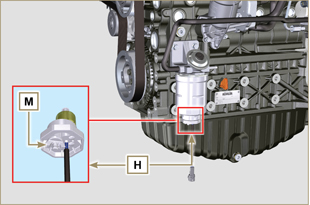 Fig 2.39 |
||||||||||||||||||||||||||||||||||||||||
|
2.14.6 Fuel temperature sensor on the fuel injection pump
Important
Tab. 2.36 reports the electrical resistor values according to the fuel’s temperature.
Tab.2.36
|
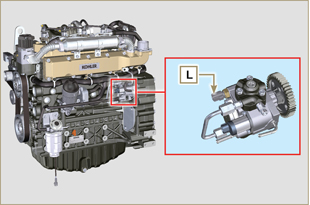 Fig 2.40 |
||||||||||||||||||||||||||||||||||||||||
| 2.14.7 Oil pressure switch Oil pressure switch N is assembled on the crankcase near to the injection pump. It is a N/C sensor, calibrated at 0.6 bar ± 0.1 bar. With oil low pressure the sensor closes the electrical circuit and the warning lamp in the panel board switches on. |
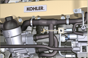 Fig 2.41 Fig 2.41 |
||||||||||||||||||||||||||||||||||||||||
|
2.14.8 Coolant temperature sensor It is used by the ECU in order to obtain information regarding the coolant temperature (from PIN R).
NOTE: R refers to the pin where it is possible to measure the electrical resistor.
|
NOTE: R indicates the pin where it is possible to measure electrical resistance. |
||||||||||||||||||||||||||||||||||||||||
|
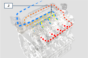
2.14.9 EGR-T sensor (versions with DPF filter only) The EGR-T J sensor is placed on the air intake manifold after the EGR gas inlet and measures the temperature of the air mixed with EGR gas coming from the turbocharger. Tab. 2.43b shows the electric resistance values based on the intake air temperature.
Tab 2.43b
|
Fig 2.48a
|
||||||||||||||||||||||||||||||||||||||||
|
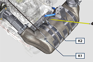
2.14.10 EGTS sensor (yellow - black)
The EGTS sensors K1 and K2 are placed on the ATS system, K1 with black wire before the DOC, K2 with yellow wire after the DOC. They are both needed for the DPF filter regeneration strategies. Tab. 2.37b shows the electric resistance values based on the intake air temperature.
Tab 2.43c
|
Fig 2.48b
|
||||||||||||||||||||||||||||||||||||||||
|
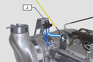
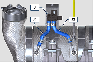
2.14.11 Sensore Delta-P Delta-P sensor
The Delta-P sensor J detects the clogging level of the DPF filter.
Operating temperature: -30°C - +120°C.
Important
|
Fig 2.48c
Fig 2.48c |
||||||||||||||||||||||||||||||||||||||||
|
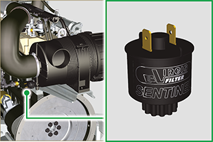
2.14.12 Air cleaner clogging switch
NOTE: Component not necessarily supplied by KOHLER.
|
|
||||||||||||||||||||||||||||||||||||||||
 Fig 2.42
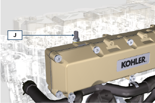

 Loading