
1
General information

2
Technical information
3
Safety information
4
Storage information
5
Information regarding discharge of liquids
6
Information for replacing the functional units
7
Information for disassembly
8
Information about overhauling
9
Assembly information
10
Fluids filling information
11
Information about optional components
12
Information on adjustments
13
Tools information
14
Information about failures
15
Glossary

Fuel system
2.9.1 Injection circuit (pressure 2000 bar) (Fig 2.4)
The materials of the fuel system components (pipes, tank, filters, etc.) and any surface treatments must be free from chemical elements that, transported in the fuel, compromise the operation of the injectors over time (hole clogging).
The most critical chemical element is Zinc (Zn), therefore it is forbidden to use galvanised components.
Other damaging elements are indicated in the table below.
Tab 2.11
| POLLUTANTS | LIMIT VALUES OF PRESENCE IN FUEL | LIMIT VALUE |
| Zn (Zinc) |
|
Zn ≤ 0.3ppm |
| Pb (Lead) |
|
Pd ≤ 0.3ppm |
| Na (Sodium) |
|
Na + K ≤ 0.3ppm |
| K (Potassium) | ||
| Ca (Calcium) |
|
Ca + Mg ≤ 0.3ppm |
| Mg (Magnesium) | ||
| Cu (Copper) |
|
Cu ≤ 0.3ppm |
| Ba (Barium) |
|
Ba ≤ 0.3ppm |
| P (Phosphorus) |
|
P ≤ 0.3ppm |
| Na - K - Ca - Mg - P |
These metals are regulated in EN14214 |
|
 Important
- The high pressure supply injection system is highly susceptible to damage if the fuel is contaminated.
- It is crucial that all components of the injection circuit are thoroughly cleaned before the components are removed.
- Thoroughly wash and clean the engine before maintenance.
- Contamination in the injection system may cause a reduction in in performance or engine faults.
- If the engine is cleaned with high pressure washer, then the nozzle must be kept at a minimum distance of 200mm from the surface, and not directed at electrical components and connectors.
|
The fuel supply system is under low pressure from fuel tank 1 to the high-pressure fuel injection pump 5.
NOTE: The representation of fuel tank is purely indicative. Component not necessarily supplied by KOHLER.
|
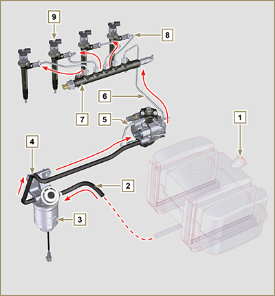 Fig 2.4 |
||||||||||||||||||||
|
2.9.2 Fuel return circuit
NOTE: The representation of fuel tank is purely indicative. Component not necessarily supplied by KOHLER.
|
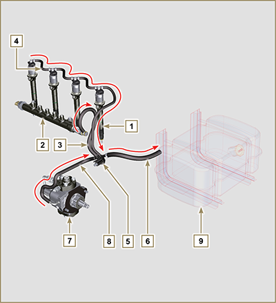 Fig 2.5 |
|
2.9.3 High-pressure injection pump (2000 bar)
Important
NOTE: In the event of leakage from the high pressure circuit do not intervene when the engine is running, but turn it off and wait 5 - 10 minutes before checking the leakage.
The inlet pressure to the high pressure pump must be between -250 mbar (suction pump without electric supply) and 200 mbar (with electric pump power) to the high pressure rail. The high pressure pump is operated via the pump control gear and sends high pressure fuel to the common rail.
NOTE: The supply tube (on union 8) and fuel return (on union 9), have different diameters.
|
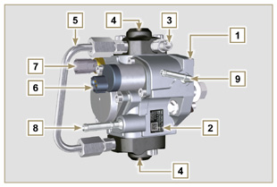 Fig 2.6  Fig 2.7 |
|
2.9.4 Electronic injector
Important
|
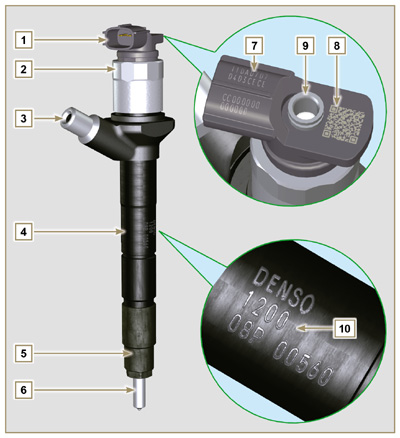 Fig 2.8 Tab 2.15
|
||||||||||||||||||||||
|
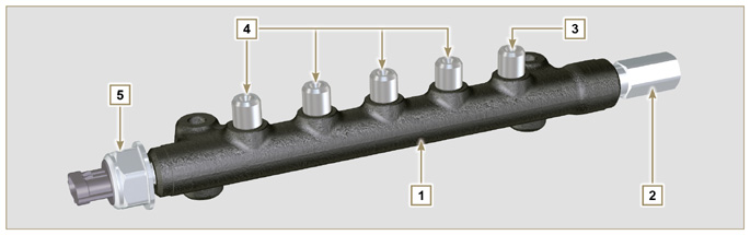
2.9.5 Common Rail
The pressure sensor 5 measures the pressure of the fuel in the Common Rail.
Important
|
|||||||||||||||||||||||
|
2.9.6 Fuel filtering |
|||||||||||||||||||||||||||
|
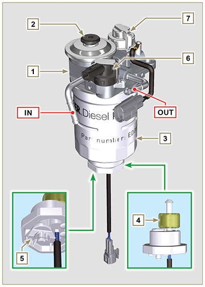
2.9.6.1 Fuel filter
Tab 2.18 Cartridge characteristics
|
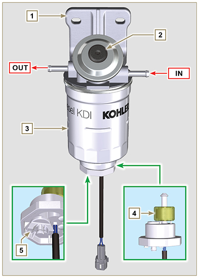 Fig 2.10 |
||||||||||||||||||||||||||
|
2.9.6.2 Fuel pre-filter (optional)
The fuel pre-filter is situated on the engine or may be assembled on the frame of the vehicle, and is always coupled with the electric pump.
2.18b
2.18c Cartridge characteristics
|
2.10b |
| 2.9.7 Electric fuel pump (optional) When the electric fuel pump is installed in a diesel engine, one must:
Tab 2.19
|
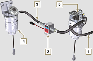 Fig 2.11 |
||||||||||||
|
2.9.8 Guards for fuel injection circuit components
Important
|
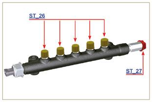 Fig 2.13 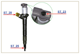 Fig 2.14 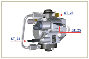 Fig 2.15 |

 Loading