=
Search

Electronic injector replacement

 Important
  • Before proceeding with operation, read Par. 3.3.2.
  • In the event of the electronic injectors being disassembled (not necessarily replaced) their position with respect to individual cylinders must not be changed when re-assembled. Refer to the reference between each injector and respective cylinder number.
  • Seal all injection component unions as illustrated in Par. 2.9.8 during disassembly.
  • Handle the components as described in Par. 2.17.
  • Replace all seal gaskets after each assembly for all components on which they are provided.
  • The high pressure pipes must be replaced every time they are disassembled.
  • Before disassembling the electronic injectors, make sure the new high pressure pipes are available.
  • If a new (or different) electronic injector is fitted on the engine, the new calibration data must be entered in the ECU through a specific instrument (ST_01).
  • Electronic injectors are not repairable.
  • This procedure may be performed on one or more electronic injectors.

    NOTE:  In the event of a leak upon replacement (oil - coolant - fuel - air), do not intervene with the engine running, but stop it and wait for 5/10 minutes before checking and solving the problem.

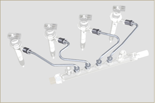
Fig 6.1
6.1.1 Fuel return pipes disassembly (Common Rail/electronic injectors)

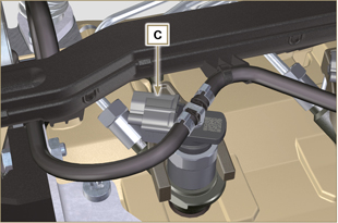
  1. Disconnect the connector C.

Fig 6.2
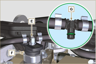
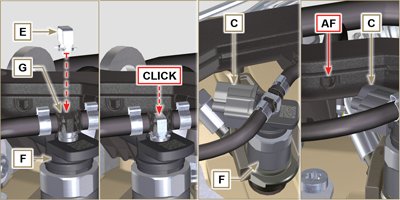
  1. Remove clips E from the electronic injector F.
  2. Disconnect the junction G from the electronic injector F.

  Warning
  • After removing the fittings, the clips E must automatically return to their initial position; otherwise they must be replaced.


  1. Seal all injection component unions as illustrated inPar. 2.9.8.

Fig 6.3

6.1.2 High pressure fuel pipes disassembly (Common Rail/electronic injectors)


  Danger
  • The fuel injection circuit is under high pressure, use safety protections as described in Par 3.4.3.
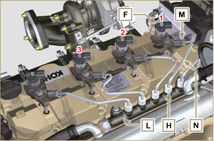
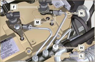
  • Ensure that the Common Rail is not under pressure by slowly and carefully unscrewing one of the nuts H.

  1. Undo the nut H on the Common Rail L and then the nut M on the electronic injector F and remove the pipe N.

  Important
  • In the event that the electronic injectors are disassembled (not necessarily replaced), mark them with the relevant cylinder number from which they originate so as not to confuse them during re-assembly.
  • Seal all injection component unions as illustrated in Par. 2.9.8.

Fig 6.4

6.1.3 Electronic injectors disassembly


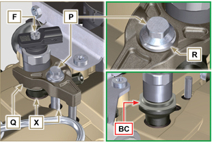
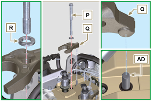
  1. Undo and remove the screw P with the washer R e and then the bracket Q.


  Important

  • Be careful not to damage the gaskets X.
  • Replace rings X, if damaged.

2. Pull out the electronic injector F.

NOTE:
Should you be unable to remove the electronic injector (acting only on point BC), use an open-ended spanner (Ø 34 mm), by applying small rotations to unblock the component.


3. Seal all injection component unions as illustrated in Par. 2.9.8.
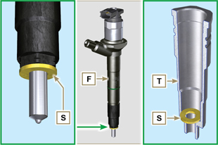
4. Ensure that gasket S has remained in the correct position (Fig. 6.6). Otherwise, recover the gasket from inside the electronic injector T manifold.


Fig 6.5


Fig 6.6

NOTE: Click by side to play the procedure.

6.1.4 Electronic injector assembly

  Important
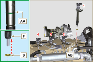
  • Always replace and lubricate the gaskets AA and S of the electronic injectors F with fuel, every time they are replaced.
  • Reposition the electronic injectors (not replaced) by following the references made for disassembly, as indicated in Par. 6.1.2.
  • If the engine is painted or protected with clear paint, clean the paint off the diesel injector F near to the part in contact with the gasket AB.
  1. Insert the gasket S on the electronic injectors F (Fig. 6.7).
  2. Insert electronic injector F into manifold T, being extra careful not to damage gasket AB and direct it as indicated in Fig. 6.7.


NOTE: to replace gaskets AB, follow the operations in Para. 7.12.1 and 9.5.9.


Fig 6.7

6.1.5 High pressure fuel pipes assembly


  Important
  • Always replace the pipes N after each assembly.
  • If the engine is painted or protected with clear paint, replace the fastening screws P to ensure the gaskets are sealed properly.

  1. Position tube N in the Common Rail seat of the electronic injector; correct the position of the electronic injector by means of the entrance of the electronic injector unions F and Common Rail L.
  2. Apply the nuts H and M by hand without tightening them.
  3. Position the fastening brace of electronic injectors Q on capscrew surface AD, insert capscrews P in brace Q inserting washer R.

Fig 6.8
  Important
  • Ensure that brace S is perfectly positioned onto the electronic injector.

4.  Tighten the fixing screws P of the electronic injector bracket (tightening torque at 20 Nm).
5.  Tighten the nut M (tightening torque at 25 Nm).
6.  Tighten the nut H (tightening torque at 30 Nm).


   Important

  • Replace the pipes N (Fig. 6.8) if the screws P are stiff when tightened.

Fig 6.9

6.1.6 Fuel return pipes assembly


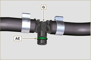
  1. Check the condition of the gaskets AE.

Fig 6.10
  1. Insert unions G onto electronic injectors F and block them with clips E.
  2. Mount the connectors C on the electronic injectors F.
     
  Warning
  • Slightly move the wiring support to check that there is no voltage in the electrical wire of connector C in correspondence with the outlet hole AF.


Fig 6.11

NOTE: Click by side to play the procedure.


Wait Loading