
1
General information

2
Technical information
3
Safety information
4
Storage information
5
Information regarding discharge of liquids
6
Information for replacing the functional units
7
Information for disassembly
8
Information about overhauling
9
Assembly information
10
Fluids filling information
11
Information about optional components
12
Information on adjustments
13
Tools information
14
Information about failures
15
Glossary

Connecting rod - piston assembly
 Important Important
|
|||||||||||||||||||||
|
8.5.1 Connecting rod dimensions check
Important
Assemble the connecting rod cap Q to the connecting rod with the half-bearings S and tighten capscrews P (tightening torque at 28 Nm). With a dial gauge, measure diameters B and D. The MAX allowed value of wear for B and D is 0.06 mm. Tab 8.6
Important
Measure value A, C, D, E and F and confront them with those described in Tab.8.6. |
 Fig 8.9 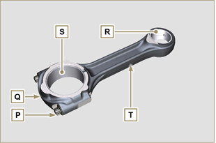 Fig 8.10 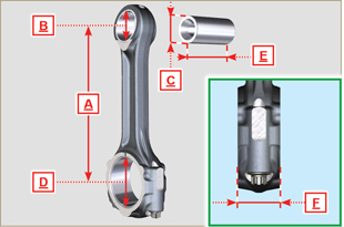 Fig 8.11 |
||||||||||||||||||||
|
8.5.2 Checking the gudgeon pin-pin axes are parallel Lubricate gudgeon pin A and bearing R (Fig. 8.10).
Insert ring U into the cylinder, measure value H (distance between the points of ring U). Important
NOTE: refer to Fig. 8.17 to locate the rings. Tab. 8.7
|
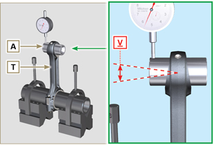 Fig 8.12 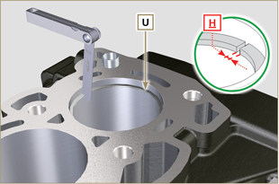 Fig 8.13 |
||||||||||||||||||||
|
8.5.4 Piston dimension check
Clean the piston thoroughly. Refer to Tab. 8.8 to establish the clearance value of the pistons with a decreased diameter.
If clearance between cylinder and piston is greater than 0,074 mm, the piston and seal rings must be replaced. Important
Tab. 8.8
|
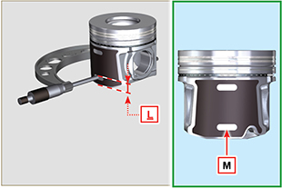 Fig 8.14 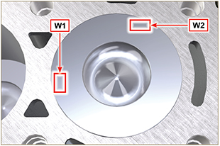 Fig 8.15 |
||||||||||||||||||||
Important
Tab 8.9
|
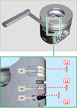 Fig 8.16 / 8.17 |
||||||||||||||||||||

 Loading