
=
Search


Lubrication circuit
|
2.10.1 Lubrication circuit diagram
|
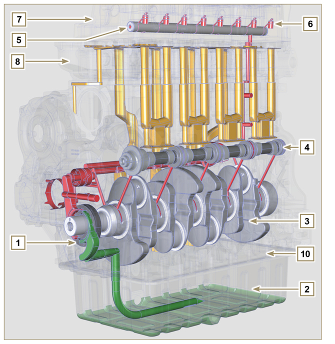 Fig 2.12 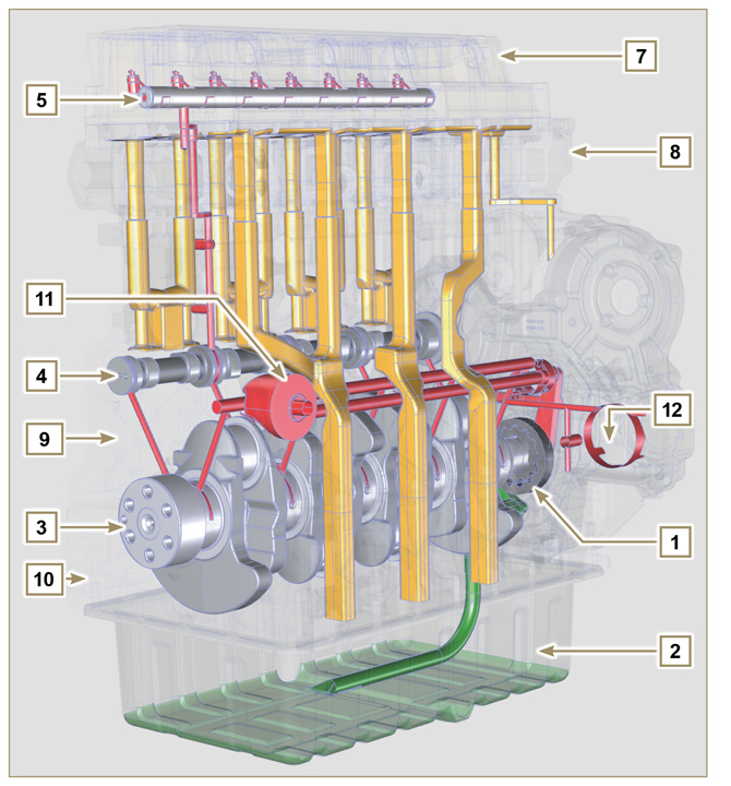 Fig 2.13 |
||||||||||||||||||||||||||||||||||
|
NOTE: Click by side to play the procedure. |
|||||||||||||||||||||||||||||||||||
|
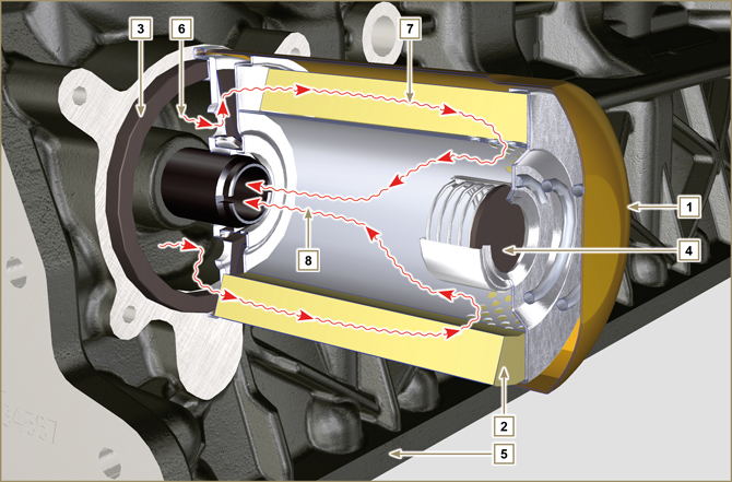
2.10.2 Oil pump
The oil pump rotors are trochoidal (with lobes) and are activated from the crankshaft by means of the key.
|
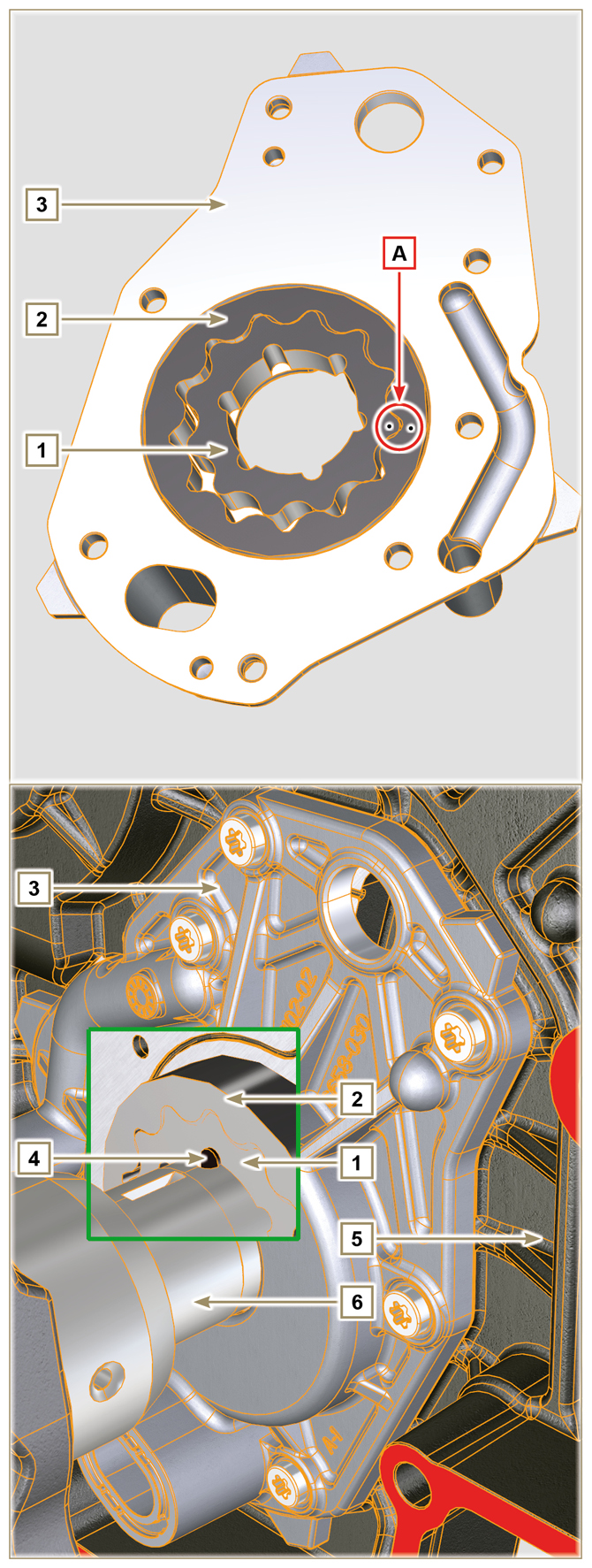 Fig 2.14 |
|
2.10.3 Oil filter
|
|||||||||||||||||||||||||||
Tab 2.20
|
Tab 2.21
|
||||||||||||||||||||||||||

 Loading