
=
Search


Cooling system
2.11.1 Cooling system schematics
| External water | |
| Exhaust gas | |
| Coolant |
|
Fig. 2.16 Fig. 2.18 |
Fig. 2.17 Fig. 2.19 |
|
Fig. 2.21 |
|
|
Fig. 2.20 Fig. 2.22 |
|
|
Tab 2.22
|
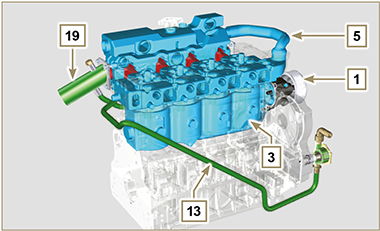
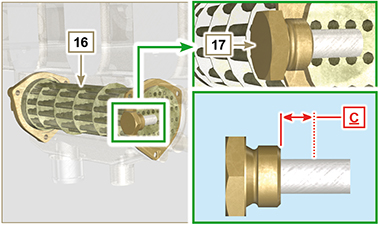
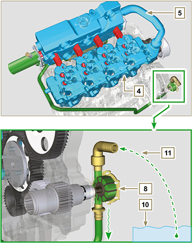
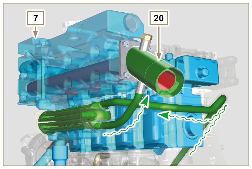
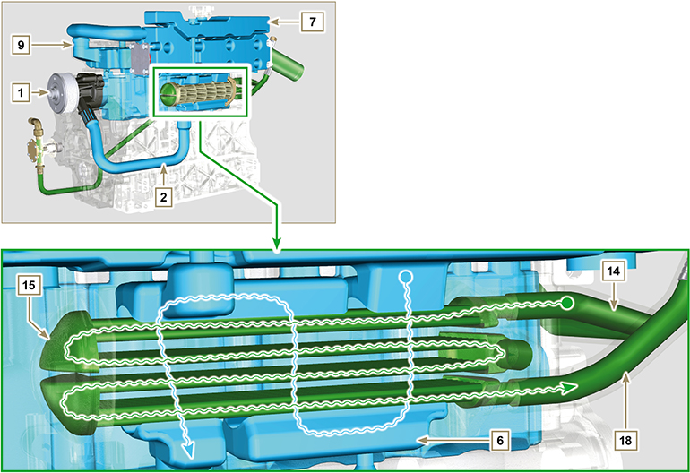
2.11.1.1 Operation Pump 1 circulates the coolant inside engine ducts and cooled exhaust manifold 7. Pump 8 draws fresh water 11 from outside the machine or vessel 10 and sends it to the radiator 16 of the cooled exhaust manifold 7. Radiator 16 cools the coolant 6 by externally passing water inside it. Cooling is obtained by passing the coolant 6 inside specific passages in the exhaust manifold 7 through radiator 16 (Fig. 2.18). External water 15 also flows in the specific passages inside the radiator 16, thus improving thermal exchange between the coolant 6 and external water 15, increasing the cooling performance of the coolant 6. Also, inside the ducts reserved for external water 15, there is a zinc anode that prevents corrosion of the parts in contact with external water 15. Then the water from the radiator 18 enters Raiser 19, which mixes with the exhaust gases along the exhaust gas line.  Important Important• It is recommended to comply with the maintenance intervals described in Par. 2.8. • The zinc anode must be replaced when level C (Fig. 2.18) is below 15 mm. |
||||||||||||||||||||||||||||||||||||||||||
|
2.11.2 Coolant pump
|
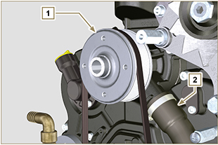 Fig 2.23 |
||||||||||||||||||||||||||||||||||||||||||
|
2.11.3 Thermostatic valve
Opening temperature +79° ± 2°C. |
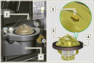 Fig 2.24 |
||||||||||||||||||||||||||||||||||||||||||
|
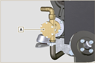
2.11.4 External water pump
|
|

 Loading