
=
Search


Intake and exhaust circuit
|
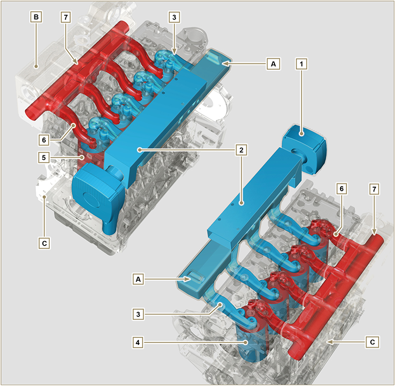 Fig 2.26 |
 Important Important
Clean air is sucked by means of an intake manifold and via ducts in the cylinder head, enters the cylinders. Compressed air inside the cylinders and mixed with the fuel transforms into Gas after combustion. Gas is expelled from the cylinders and sent to the exhaust manifold, which expels the gas towards the exhaust muffler. |
Tab 2.25
|
||||||||||||||||||||||
|
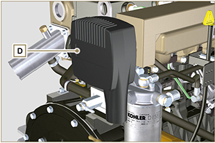
2.12.1 Air filter
Important
|
Fig. 2.27 |
||||||||||||||||||||||
|
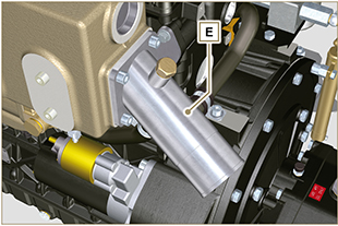
2.12.2 Raiser
Raiser E enables external water to enter the discharge line duct, and due to the pressure of exhaust gas external water can be easily eliminated. |
Fig. 2.28 |

 Loading