
=
Search
1
General information

2
Technical information
3
Safety information
4
Storage information
5
Information regarding discharge of liquids
6
Information for replacing the functional units
7
Information for disassembly
8
Information about overhauling
9
Assembly information
10
Fluids filling information
11
Information about optional components
12
Information on adjustments
13
Tools information
14
Information about failures
15
Glossary

Electrical components
|
2.15.1 Alternator
|
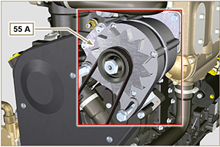 Fig 2.43 |
||||||||||||||||||||||||||||||||||
2.15.2 Starter Motor
|
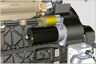 Fig 2.44 |
||||||||||||||||||||||||||||||||||
|
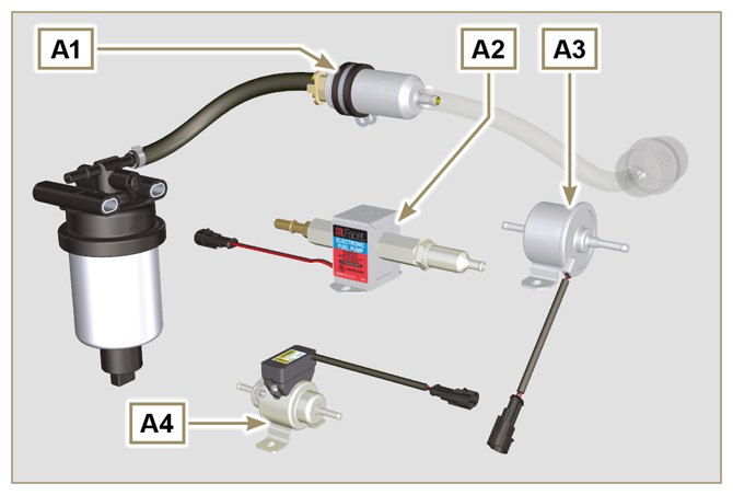
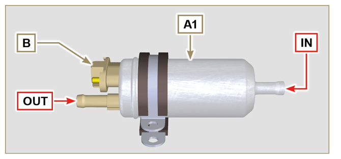
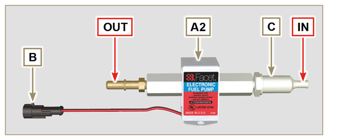
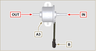
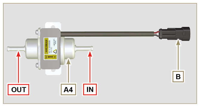
2.15.3 Electric pump
Tab 2.31
Tab 2.32
|
Fig 2.46
Fig 2.47
Fig 2.48
Fig 2.49 |
||||||||||||||||||||||||||||||||||
|
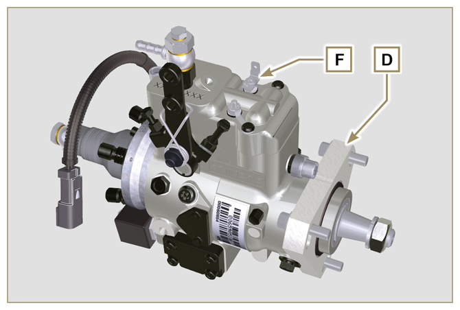
2.15.4 Electro-Stop
The electro-stop F device is part of injection pump D; it turns off the engine by blocking the flow of fuel into pump D. |
Fig 2.50 |
||||||||||||||||||||||||||||||||||
|
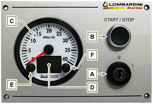
2.15.5 Control panel
Tab. 2.33 shows the control panel components.
|
Fig 2.51 |
||||||||||||||||||||||||||||||||||
|
Tab. 2.34 shows data that can be consulted on display D by pressing push button E.
|
|||||||||||||||||||||||||||||||||||


 Loading