
1
General information

2
Technical information
3
Safety information
4
Storage information
5
Information regarding discharge of liquids
6
Information for replacing the functional units
7
Information for disassembly
8
Information about overhauling
9
Assembly information
10
Fluids filling information
11
Information about optional components
12
Information on adjustments
13
Tools information
14
Information about failures
15
Glossary

Fuel system
|
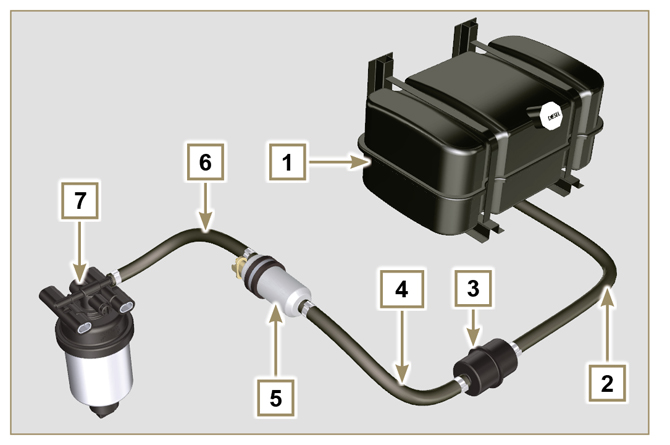
2.9.1 Supply system
 Important Important
|
|
The fuel supply system is under low pressure from the tank 1 to the high-pressure fuel injection pump 5.
NOTE: The representation of fuel tank is purely indicative. Component not necessarily supplied by KOHLER.
|
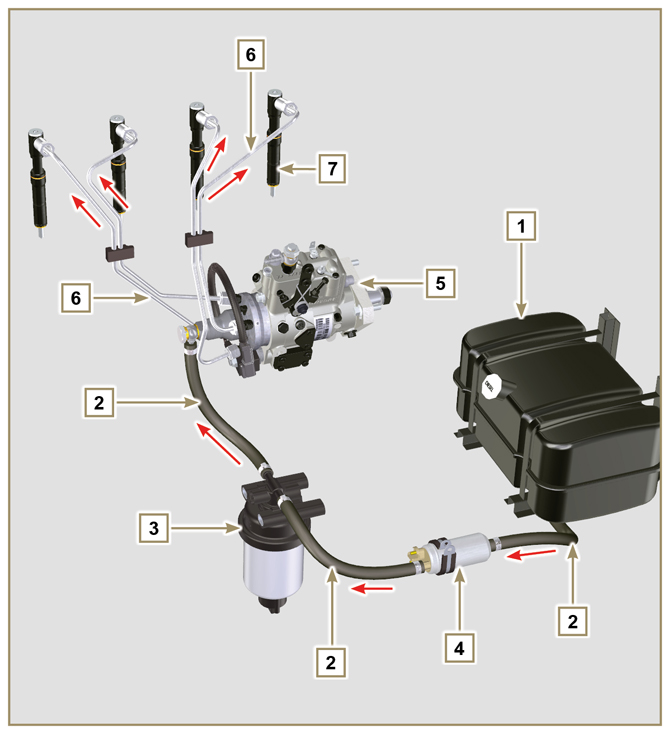 Fig 2.4 |
||||||||||||||||
|
2.9.2 Fuel return circuit
NOTE: The representation of fuel tank is purely indicative. Component not necessarily supplied by KOHLER.
|
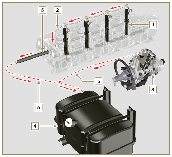 Fig 2.5 |
|
2.9.3 Injection pump
|
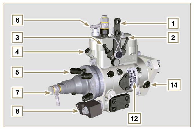 Fig 2.6 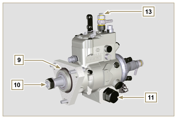 Fig 2.7 |
|
2.9.4 Injector
Opening pressure: 260-268 bar (3770-3886 PSI)
Important
Tab 2.15
|
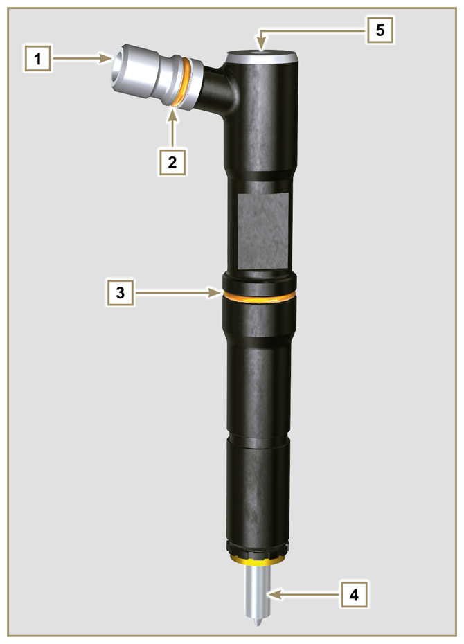 Fig 2.8 |
|
2.9.5 Fuel filter
Tab 2.17 Cartridge characteristics
|
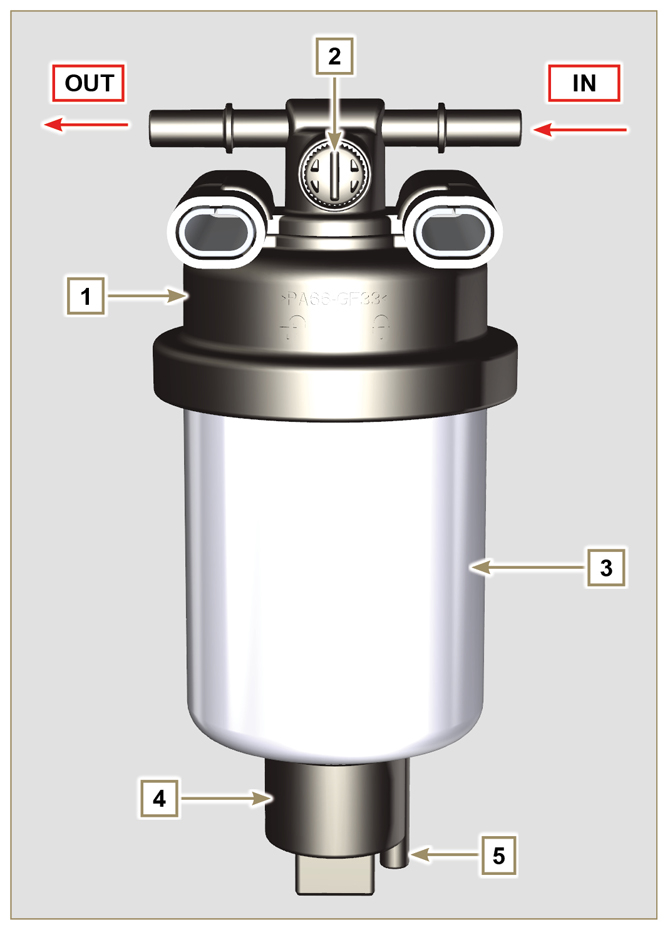 Fig 2.9 |
|
2.9.6 Electric fuel pump (optional)
Tab 2.18
|
|
||||||||||||||||
|
2.9.7 Guards for fuel injection circuit components
Important
|
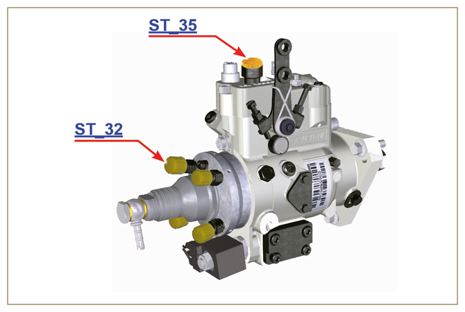 Fig 2.11 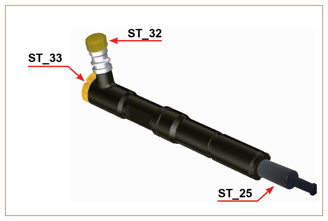 Fig 2.12 |

 Loading