
1
General information

2
Technical information
3
Safety information
4
Storage information
5
Information regarding discharge of liquids
6
Information for replacing the functional units
7
Information for disassembly
8
Information about overhauling
9
Assembly information
10
Fluids filling information
11
Information about optional components
12
Information on adjustments
13
Tools information
14
Information about failures
15
Glossary

Injectors and injection pump replacement
 Important Important
|
 Fig 6.1 |
||||||||||||||||||||||||||||||||||||||||||||||||||||||||||||
|
6.1.1injection fuel pump disassembly (injection pump/injectors)
|
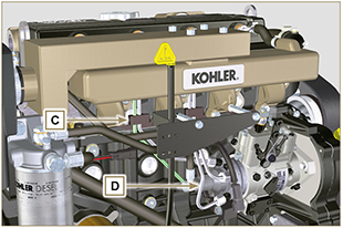 Fig 6.2 |
||||||||||||||||||||||||||||||||||||||||||||||||||||||||||||
|
 Fig 6.3 |
||||||||||||||||||||||||||||||||||||||||||||||||||||||||||||
|
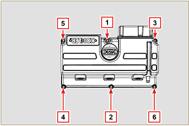
6.1.2 Rocker arms cover disassembly
|
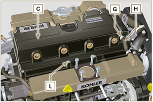 Fig 6.4 |
||||||||||||||||||||||||||||||||||||||||||||||||||||||||||||
|
6.1.3 Fuel return pipes disassembly
|
 Fig 6.5 |
||||||||||||||||||||||||||||||||||||||||||||||||||||||||||||
|
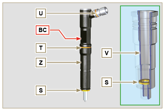
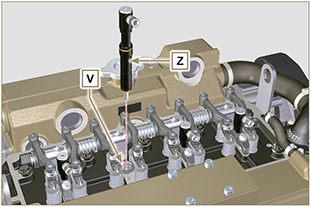
6.1.4 Injectors disassembly
NOTE: Should you be unable to remove the injector (acting only on point BC), use an open-ended spanner (11 mm), by applying small rotations to unblock the component.
NOTE: If the washer S is not found on the injector Z, recover it from inside the sleeve V. |
Fig 6.6
|
||||||||||||||||||||||||||||||||||||||||||||||||||||||||||||
6.1.5 Injection pump disassembly Important
NOTE: Do not tighten the capscrew P.
Fig 6.9
Tab. 6.1
|
Fig 6.8
Fig 6.10
|
||||||||||||||||||||||||||||||||||||||||||||||||||||||||||||
|
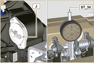
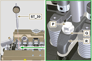
5. Find the TDC through tool ST_30, then bring the dial gauge indicator to 0.
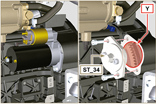
NOTE: The value indicated in Tab. 6.1 must be reached by rotating the shaft with the piston in compression phase. Use the ST_34 tool to totate the crankshaft. |
Fig 6.11
Fig 6.12 |
||||||||||||||||||||||||||||||||||||||||||||||||||||||||||||
|
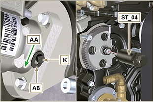
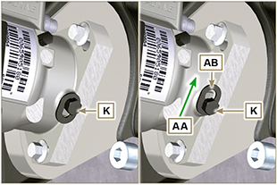
8. Lock the ST_34 tool through J screws and ensure that the crankshaft does not rotate, which would alter the correct advance value. If this happens, repeat the instructions described in points 4, 5, 6, 7 and 8. 11. Undo the capscrew K and shift the slotted plate AB in the direction of arrow AA. 12. Tighten screw K to block the pump (tightening torque to 12 Nm).
Important
13. Screw the tool ST_04 on the gear AE. 14. Loosen the screws AF.
|
Fig 6.13
Fig 6.14 |
||||||||||||||||||||||||||||||||||||||||||||||||||||||||||||
|
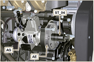
15. Tighten the screw of tool ST_04 to disconnect the injection pump AG from the high pressure pump control gear AE.
|
Fig 6.15
|
||||||||||||||||||||||||||||||||||||||||||||||||||||||||||||
|
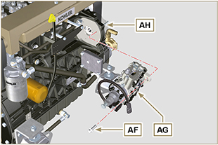
6.1.6 Injection pump assembly
1. Mount the injection pump AG, inserting the shaft AP in the gear AE.
Important
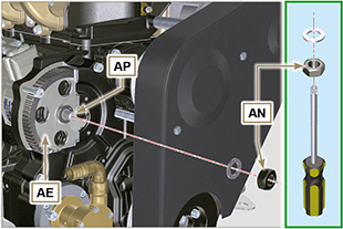
2. Clamp the screws AF on the crankcase AH (tightening torque at 25 Nm). 3. Ensure that the correct advance value has remained unchanged, tighten nut AN on shaft AP (as shown in Fig.6.17, is allowed the aid of a screwdriver to guide the nut AN on the shaft AP in order to avoid the fall of it into the timing cover AQ - tightening torque at 70 Nm). |
Fig 6.16
Fig. 6.17 |
||||||||||||||||||||||||||||||||||||||||||||||||||||||||||||
|
4. Undo the capscrew K and shift the slotted plate AB in the direction of arrow AA.
|
Fig 6.18 |
||||||||||||||||||||||||||||||||||||||||||||||||||||||||||||
|
NOTE: Always replace the gasket AJ after each assembly.
|
Fig 6.19 |
||||||||||||||||||||||||||||||||||||||||||||||||||||||||||||
|
6.1.7 Injector assembly
Important
|
Fig 6.20
|
||||||||||||||||||||||||||||||||||||||||||||||||||||||||||||
|
2. Fit the injector Z in the sleeve V.
|
Fig 6.21 |
||||||||||||||||||||||||||||||||||||||||||||||||||||||||||||
|
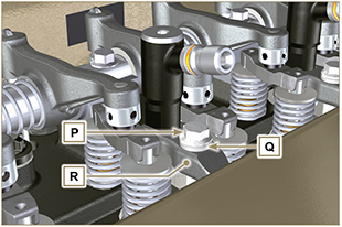
3. Assemble the parts P, Q, R and fit the parts so assembled on the injector Z. |
Fig 6.22 |
||||||||||||||||||||||||||||||||||||||||||||||||||||||||||||
|
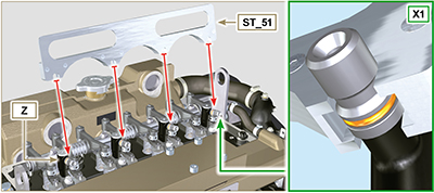
4. Insert tool ST_51 on the injectors junctions Z (detail X1). 5. Tighten the screw P (tightening torque to 20 Nm) |
Fig 6.23
|
||||||||||||||||||||||||||||||||||||||||||||||||||||||||||||
|
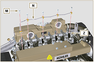
6.1.8 Assembly of the injector return pipes
|
Fig 6.24 |
||||||||||||||||||||||||||||||||||||||||||||||||||||||||||||
|
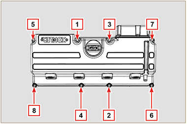
6.1.9 Assembly Rocker arm cover
Important
Important
|
Fig 6.25
Fig 6.26
Fig 6.27
Fig 6.28 |
||||||||||||||||||||||||||||||||||||||||||||||||||||||||||||
|
6.1.10 Installation of the fuel injector pipes (pump injector/injectors)
Important
|
Fig 6.29 |


 Loading