
=
Search
1
General information

2
Technical information
3
Safety information
4
Storage information
5
Information regarding discharge of liquids
6
Information for replacing the functional units
7
Information for disassembly
8
Information about overhauling
9
Assembly information
10
Fluids filling information
11
Information about optional components
12
Information on adjustments
13
Tools information
14
Information about failures
15
Glossary

External water pump impeller replacement
|
6.2.1 Disassembly
|
Fig. 6.30 |
|
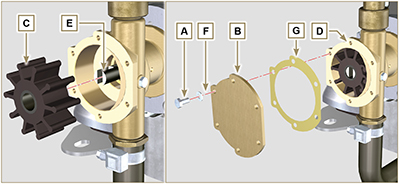
6.2.2 Assembly
|
Fig. 6.31 |
 Important
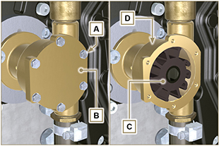

 Loading