
=
Search
1
General information

2
Technical information
3
Safety information
4
Storage information
5
Information regarding discharge of liquids
6
Information for replacing the functional units
7
Information for disassembly
8
Information about overhauling
9
Assembly information
10
Fluids filling information
11
Information about optional components
12
Information on adjustments
13
Tools information
14
Information about failures
15
Glossary

Engine block assembly
|
9.2.1 Crankshaft bushings
 Important Important
Important
|
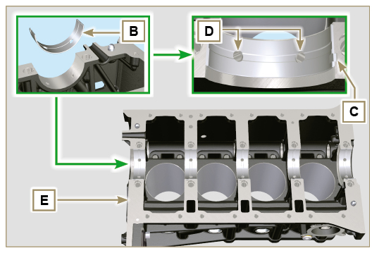 Fig 9.1 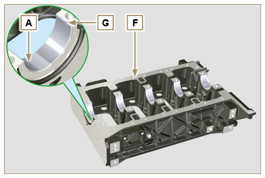 Fig 9.2 |
|
9.2.2 Tappets
|
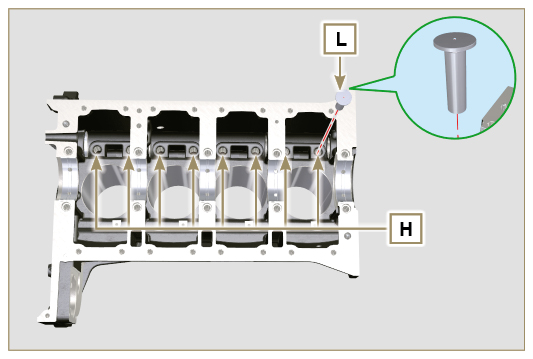 Fig 9.3 |
|
9.2.3 Camshaft
|
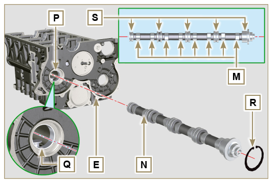 Fig 9.4 |
|
9.2.4 Vent compartment closure lid
|
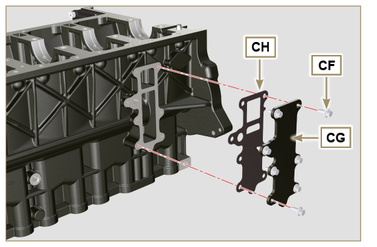 Fig 9.5 |
|
9.2.5 Crankshaft
Important
|
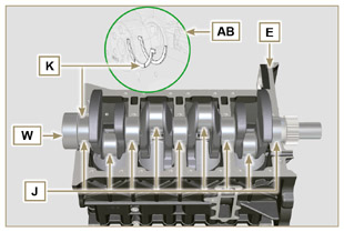 Fig 9.6 |
|
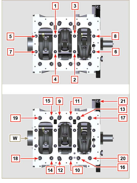
9.2.6 Lower crankcase
|
 Fig 9.7 |
|
 Fig 9.8 |
Important
|
3 Cylinders
|
|
4 Cylinders
|
|
9.2.7 Piston rings
|
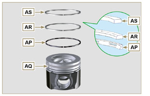 Fig 9.11 |
NOTE: do not use the segment opening with the pin hole (N)
|
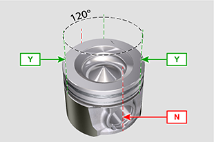 Fig 9.12 |
|
9.2.8 Piston and connecting rod
Important
|
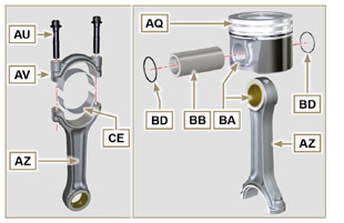 Fig 9.13 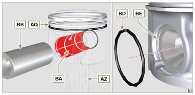 Fig 9.14 |

|
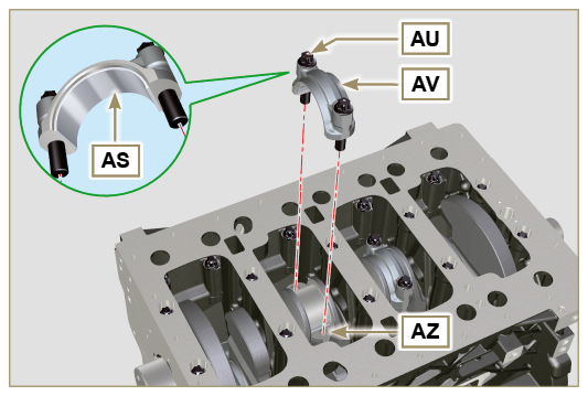
9.2.9 Piston and connecting rod assembly
Important
|
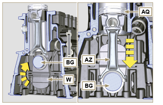 Fig 9.15 |
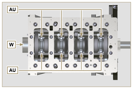
Important
|
Fig 9.16 |
Important
|
Fig 9.17 |
|
9.2.10 Crankshaft gasket flange
Important
|
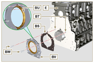 Fig 9.18 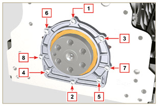 Fig 9.19 |
|
9.2.11 Flange 3rd PTO
Important
|
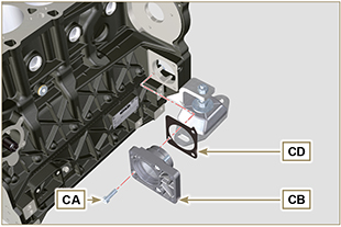 Fig 9.20 |

 Loading