
=
Search
1
General information

2
Technical information
3
Safety information
4
Storage information
5
Information regarding discharge of liquids
6
Information for replacing the functional units
7
Information for disassembly
8
Information about overhauling
9
Assembly information
10
Fluids filling information
11
Information about optional components
12
Information on adjustments
13
Tools information
14
Information about failures
15
Glossary

Electric component assembly
9.13.1 Sensors and switches
|
9.13.1.1 Coolant temperature sensor
|
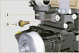 Fig 9.70 Fig 9.70 |
|
9.13.1.2 Oil pressure switch and sensor
|
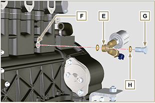 Fig 9.71 Fig 9.71 |
|
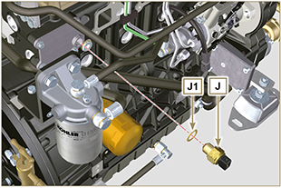
9.13.1.3 Coolant temperature switch
|
Fig 9.72 |
|
9.13.2 Belts and alternator
|
Fig 9.73 |
|
9.13.3 Electric fuel pump
|
Fig. 9.74 |
|
9.13.4 Starter Motor
 Important Important
|
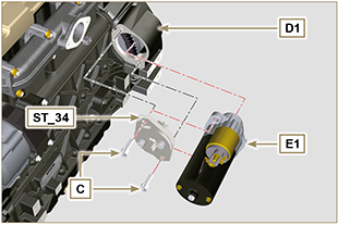 Fig 9.75 |
|
9.13.5 Electric wiring
NOTE: refer to Par. 2.13.1.3 to connect all connectors. |
|

 Loading