
=
Search
1
General information

2
Technical information
3
Safety information
4
Storage information
5
Information regarding discharge of liquids
6
Information for replacing the functional units
7
Information for disassembly
8
Information about overhauling
9
Assembly information
10
Fluids filling information
11
Information about optional components
12
Information on adjustments
13
Tools information
14
Information about failures
15
Glossary

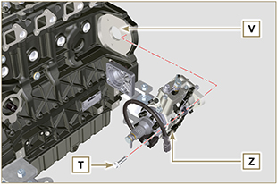
Timing system gear assembly and injection pump
|
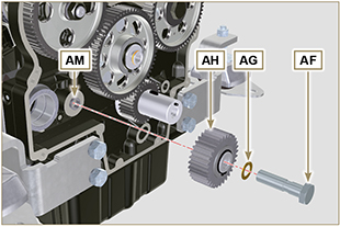
9.8.1 Timing system gear assembly
|
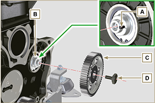 Fig 9.51 |
 Important Important
|
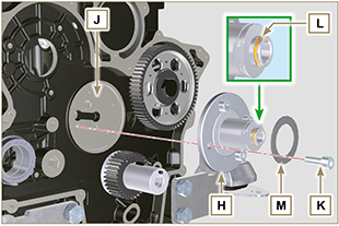 Fig 9.52 |
Important
|
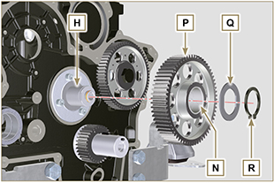 Fig 9.53 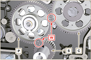 Fig 9.54 |
Important
|
Fig. 9.55 |
|
Fig. 9.56
Fig. 9.57 |
|
Fig. 9.58 |
|
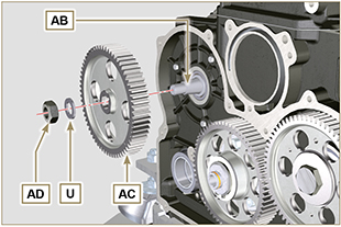
9.8.2 Injection pump
Important
NOTE: During the detection phase of the TDC, check that cylinder N° 1 is in compression phase (align the notches W as in Fig. 9.33).
|
|
|
|
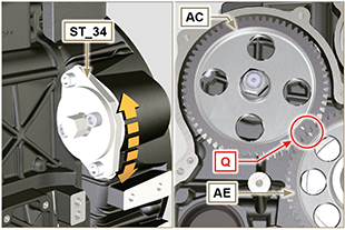
NOTE: You are not required to respect the reference Q gear AE (Fig. 9.61).
|
|

 Loading